22
Operating Manual - Elevator Door Operation AT18
13 Expansion module (Option)
13.1 Installation of the expansion module
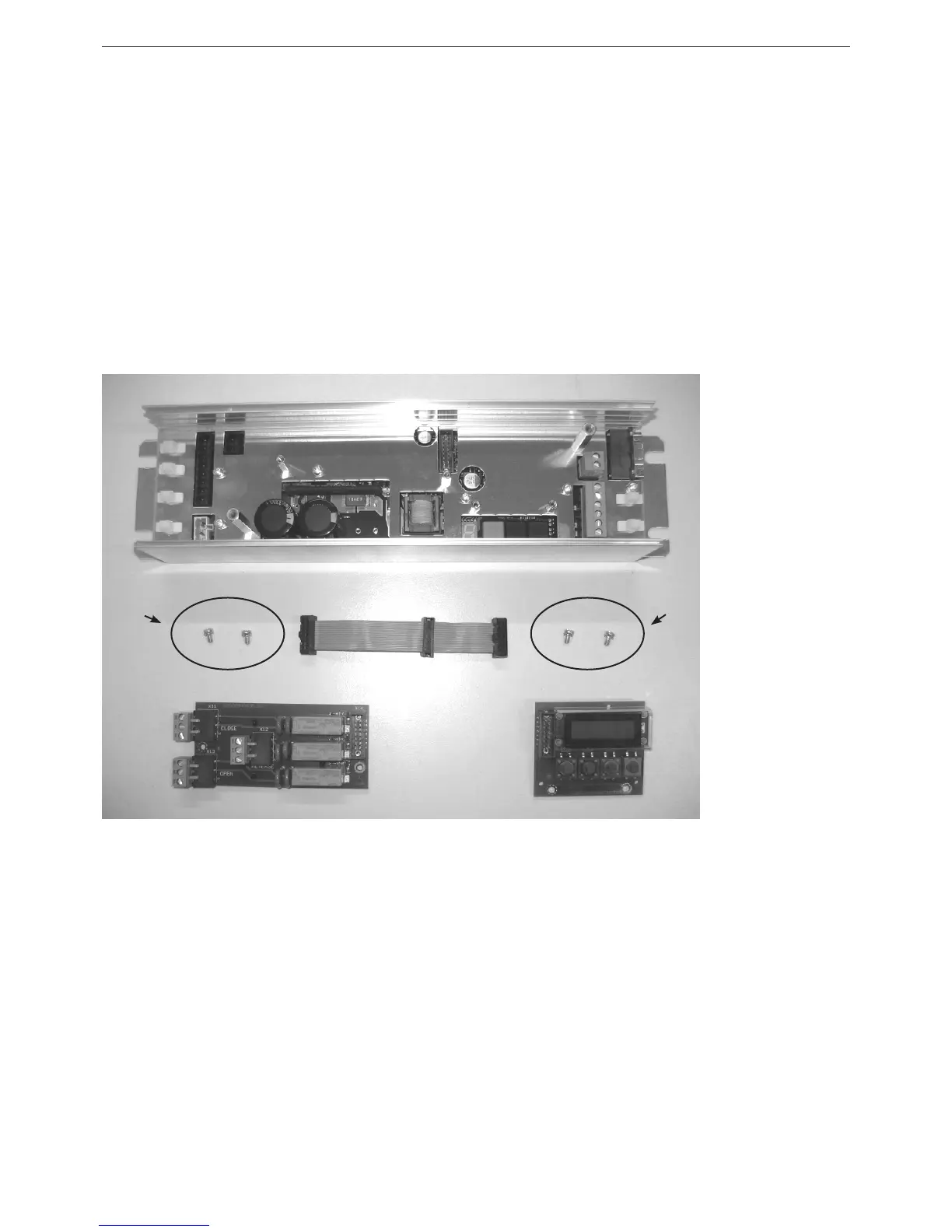
Components
1 – Basis model AT18
2 – Terminal module
3 – Relay module
4 – Flat ribbon cable with the plugs A, B and C
5 – Fastening screw for terminal module
6 – Fastening screws for relay module
Photo 3
Pin conguration of the at ribbon cable (Pos. 4):
A = Basis model AT18 (Pos. 1)
B = Terminal module (Pos. 2)
C = Relay module (Pos. 3)
A B C
1
6 5
23
4




 To Next Page