Operating Manual - Elevator Door Operation AT18
7
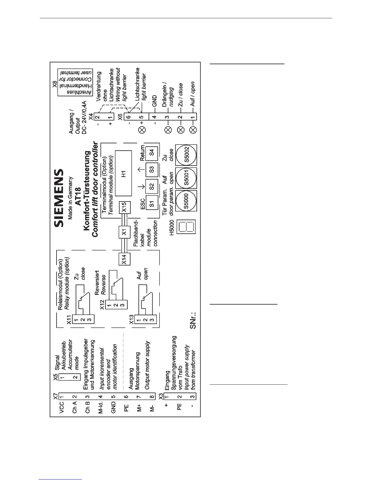
5 Overview of the operating elements
Substructure group AT18:
X1: Auxiliary module at cable
connection
X3: Mains current transformer
connection
X4: Current output 24V / 0,4A
X5: Emergency power module
input signal
X6: Input signals connection
- Light barrier
- Nudge
- Close
- Open
X7: Motor plug
X8: Connection for user terminal and
USB adapter (AT Frontend PC)
H5000: 7-segment display for door
status and error code
S5000: Door parameter button
S5001: Service button “
OPEN”
S5002: Service button “
CLOSE”
Relay module (Option):
X11: Relay output “
CLOSE”
X12: Relay output “
Reversed”
X13: Relay output “
OPEN”
X14: Flat cable connection to the
control unit
Terminal module (Option):
X15: Flat cable connection to the
control unit
H1: LCD-Display
S1-S4: Operating button for terminal
Illustration 1 module