4 Configuration and Project Engineering
4.3 Safe Torque Off (STO)
SINAMICS G120 as a Speed Axis on the S7-1500
V1.0a, Entry ID: 78788716
Copyright Siemens AG 2013 All rights reserved
4.3 Safe Torque Off (STO)
with Safety Integrated
This function is not implemented in the STEP 7 sample project. Furthermore, it is
not available for the SINAMICS G120P.
Requirements
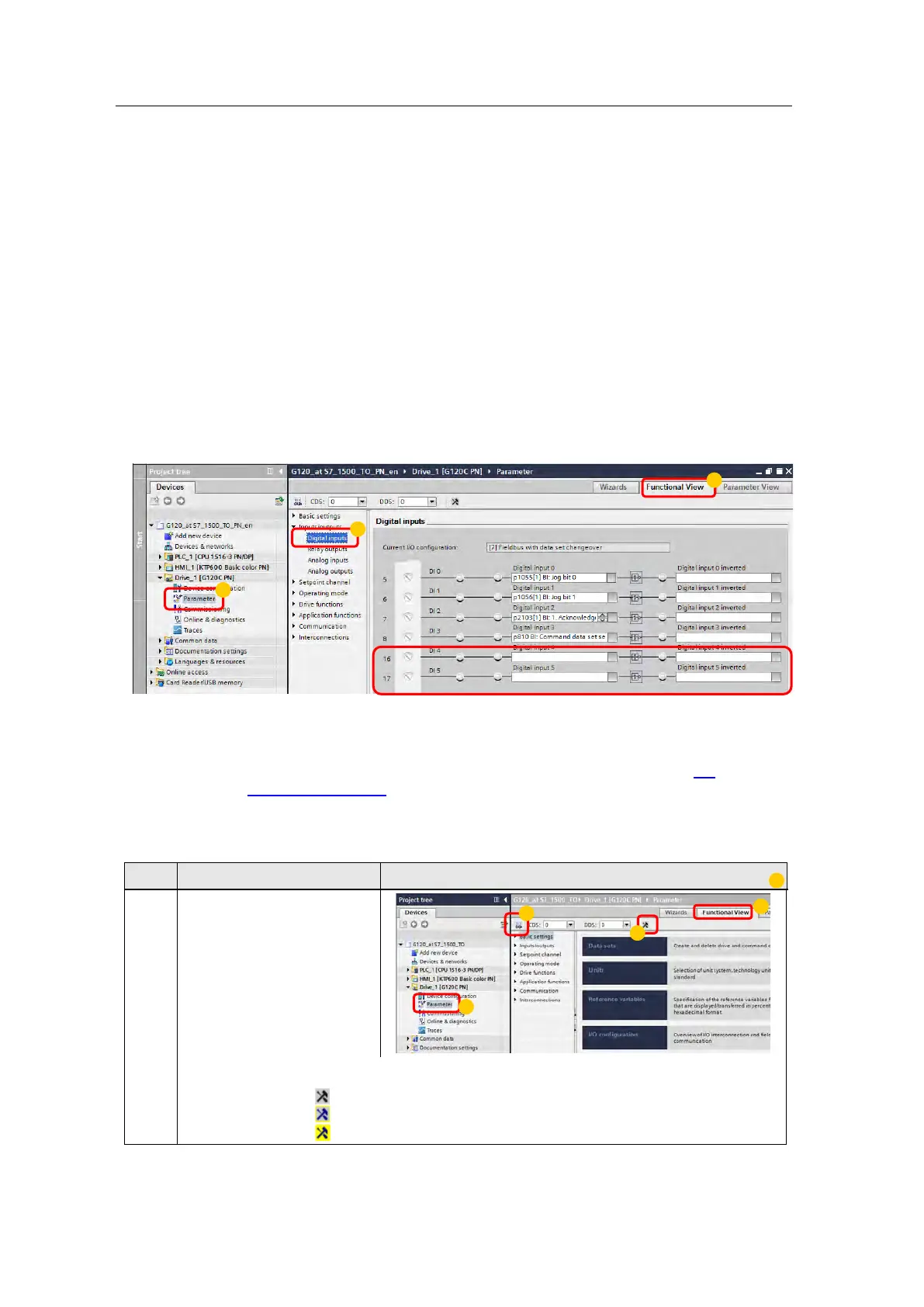
• Make sure that the digital inputs DI 4 and DI 5 (terminals 16 and 17) of the
G120 that form the fail-safe input F-DI are not assigned a “standard” function.
This is ensured in the sample project and in the factory settings.
Figure 4-1: Digital inputs
Figure 4-2
• For test purposes, apply 24V to DI 4 and DI 5 or connect an emergency stop
control device. Do not forget to connect the reference potential of inputs DI 4
and DI 5 to ground. The wiring of the signals is shown in chapter 5.1
Connection diagram.
Activating safety functions
No. Action Picture
1. 1. Navigate to the
configuration editor.
2. Select the function view.
3. Go online.
4. Activate the safety
commissioning mode.
The safety commissioning mode is displayed as follows:
The function view is not online.
The function view is online, safety functions are not activated.
Safety commissioning is active.

 Loading...


