19 / 62
BA 5060 EN 04/2011
5. Technical description
Observe the instructions in section 3, "Safety instructions"!
5.1 General description
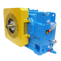
The gear unit described is a twostage helicalgear unit designed for driving an aircooler installation for
power stations. It is designed for installation in a vertical position.
The output shaft rotates in an oilpressure tube (see item 5.6.2). This prevents gear oil from escaping at
the shaft end. The oil supply to and from the gear unit is possible by means of a flangedon pump or a motor
pump.
The gear unit can be operated in both directions of rotation. Addingon a backstop
establishes the gear unit for a certain direction of rotation.
The speed range indicated to us in the design stage is covered by the use of a pump.
Onload operation of the gear units at different speeds can cause damage.
The gear units are characterised by a low noise level, which is achieved by helical gears with a high contact
ratio and a sounddamping housing.
The good temperature characteristics of the gear unit are achieved by its high degree of efficiency, large
housing surface and performancerelated cooling system.
5.2 Housing
The housing is made of cast iron; if necessary, it may also be made of steel.
The housing is made in one part. It is of torsionally rigid design and its shape imparts very favourable noise
and temperature characteristics.
The gear unit comes with the following equipment:
• Lifting eyes (adequately dimensioned for transport)
• Inspection and/or assembly cover (for inspection)
• Oil dipstick and/or oilsight glass (for oil level check
1)
)
• Oildrain cock or oildrain plug (to drain the oil)
• Wetair filter (for aeration and ventilation)
1)
Should both be available, use of the oil dipstick has priority.
Colour codes for ventilating, oil inlet, oil level and oil drainage:
Airrelief point: yellow
Oildraining point: white
Oilfilling point: yellow Lubrication point: red
Oil level: red Oil level: red

 Loading...


