5.3 Hardware components
5.3.1 Periphery board
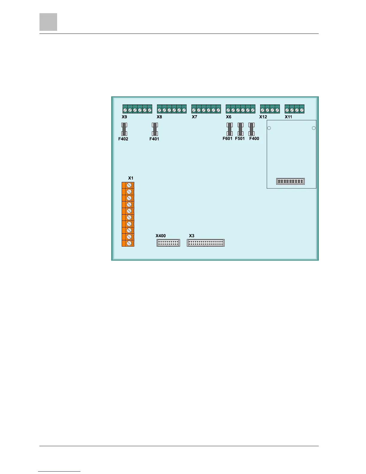
Position of connection terminals on periphery board (2-loop) of
FC722 fire control panel
Figure 7: Periphery board (2-loop) for FC722
X1 Connection of power unit
X3 Ribbon cable to PMI & mainboard (operating unit on pivot frame)
X6 Monitored outputs for acoustic signal transmitter, alarm and fault messages
X7 Changeover contacts for RT Alarm and RT Fault (remote transmission)
X8 Configurable inputs/outputs (1-4), supply voltage Vsys 1
X9 Configurable inputs/outputs (5-8), supply voltage Vsys 2
X11 C-NET loop 1 or stub 1+2
X12 C-NET loop 2 or stub 3+4
X400 Ribbon cable peripheral data bus
Fxxx SMD fuses 1A/T
 Loading...


