5.3.4 Connection of monitored acoustic signal transmitters
Assignment of connection terminals on periphery board (2-loop) of FC722 and/or
periphery board (4-loop) of FC724.
Permitted cable cross-section: 0.2…1.5 mm
2
.
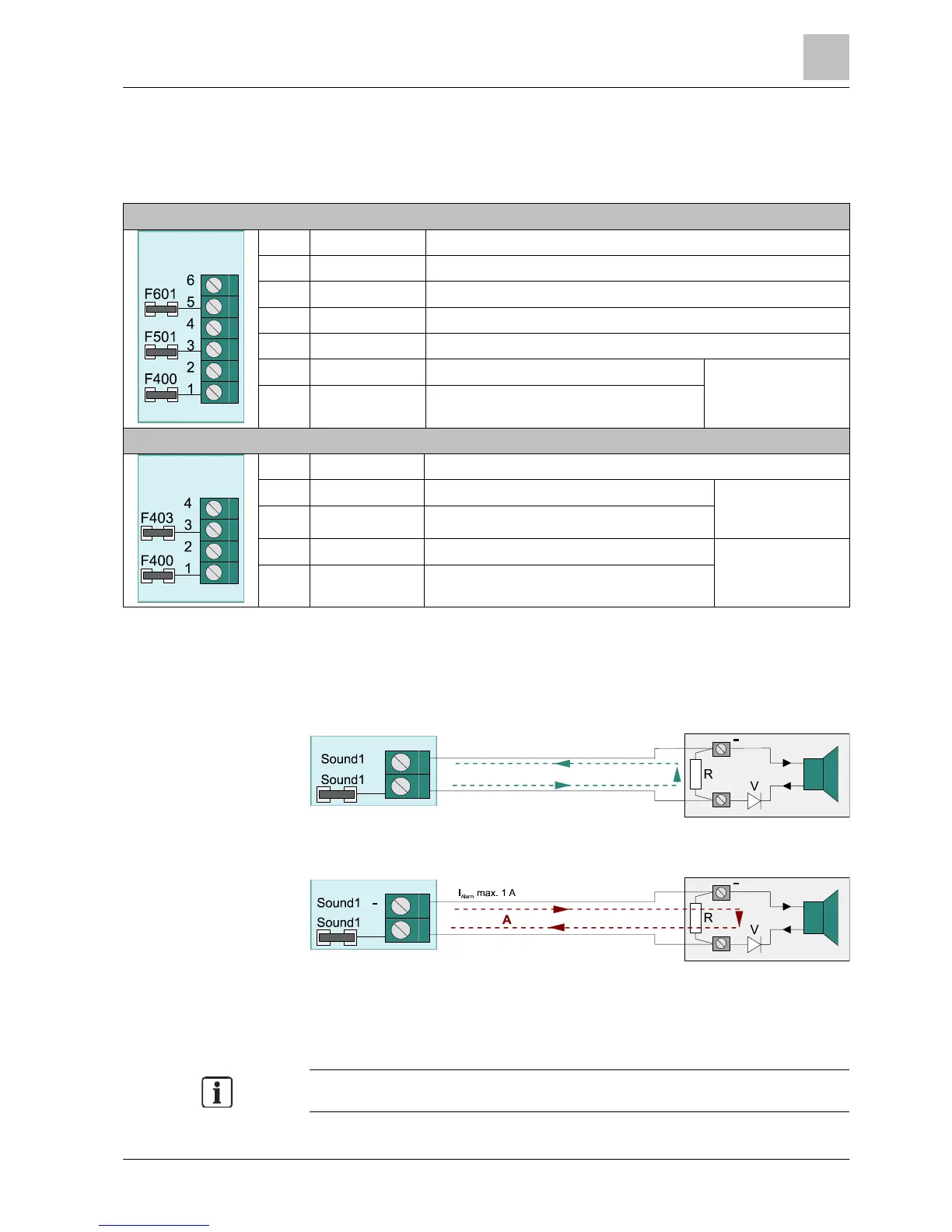
FC722
X6 Designation Description
6 FAU_OUT Output fault
5 VSYS_O Supply output for consumer fault
4 AL_OUT- Alarm output (-)
3 AL_OUT+ Alarm output (+)
2 SOUND1- Output for acoustic signal transmitter (-)
Potential-free
directional contact
Max. DC 24 V / 1 A
1 SOUND1+ Output for acoustic signal transmitter (+)
FC724
X5 Designation Description
4 SOUND2- Output for acoustic signal transmitter 2 (-)
Monitored/switchin
g positively
Max. DC 24 V / 1 A
3 SOUND2+ Output for acoustic signal transmitter 2 (+)
2 SOUND1- Output for acoustic signal transmitter 1 (-)
Monitored/switchin
g positively
Max. DC 24 V / 1 A
1 SOUND1+ Output for acoustic signal transmitter 1 (+)
Diagram showing principle
In normal operation, the connection is monitored for wire breaks and short-circuits
on the connection line. A monitoring current flows through the termination resistor
R (2.3 kOhm to 5.5 kOhm). All resistance values outside this range are recognized
as faults. The termination resistor should be connected directly to the connection
terminals of the monitored signal transmitter.
In the event of an alarm (with output activated), the polarity on the connection
terminal is reversed and the blocking diode is switched in the conducting direction.
The external signal transmitter is activated with the output voltage (DC +24 V).
Fx ⇒ SMD fuse 1 A/T (on the periphery board)
R ⇒ termination resistor (coverage area 2.3 kOhm – 5.5 kOhm)
V ⇒ blocking diode type 1N 4xxxx
M ⇒ flow of current in normal operation (monitoring)
A ⇒ flow of current during an alarm
 Loading...


