5.2 Power supply - mains voltage connection
When supplied from the factory, the power supply's internal cabling is already
connected.
Power units available
24 V DC/2.5 A, power 70 W, max. battery capacity which can be connected 17 Ah
24 V DC/5 A, power 150 W, max. battery capacity which can be connected 45 Ah
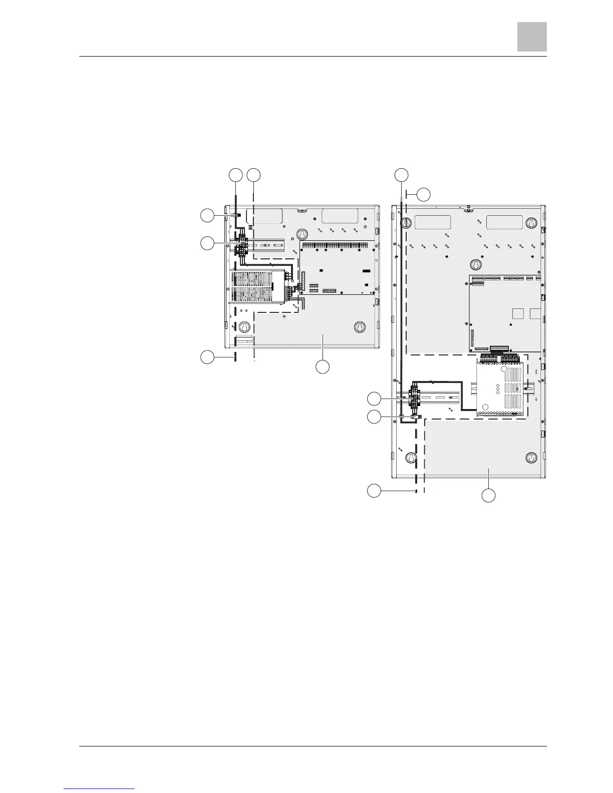
Figure 4: Mains connection in Standard and Comfort housings
1 EMC-critical zone (no high-voltage power permitted) 4 Cable strain relief for mains supply line
2
Mains connection from below (not permitted when batteries
are fitted)
5
Mains connection from above
(recommended)
3 Power supply terminals 6 EMC boundary
● The network cables must be inserted from above.
● The mains lead must be placed along the left side of the housing (observe
EMC zone boundary).
● Signal and control lines must only be fed into the housing on the right from
above or from the rear.
● Batteries must be installed in the correct positions.
● No cable openings should be made in the base of the housing, unless an
additional empty housing is mounted below the station to accommodate the
batteries.
● The mains connection voltage needed (230 V AC/115 V AC) can be found on
the station's type plate.
2
3
5 6
1
4
2
3
4
 Loading...


