Technical Instructions LME Series
Document No. LME-1000
Section 1 Page 4 SCC Inc.
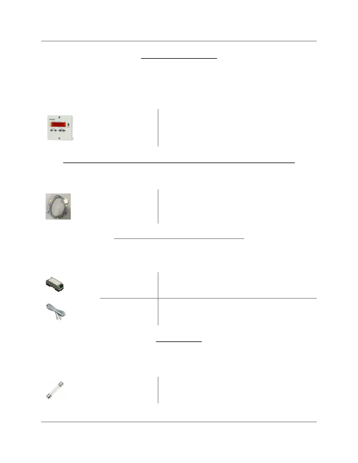
Remote Display – Optional
Each LME7 can be equipped with a remote display that provides additional status information
not shown by the integral LED display on the LME7. Either the remote display or the ACS410
software are required to change parameter settings on the LME7. See page 11 for mounting
information and panel cutout dimensions.
AZL23.00A9
Backlit remote display
Remote Display Cable – Qty (1) Required if Using the AZL23.00A9 Remote Display
This cable is required when using an AZL23 display to connect the AZL23 to the LME7 base unit.
TDCCOMBO
Pre-made 7 foot cable and adapter for connecting
the AZL23 display to the LME7 base unit
Interface Modules and Accessories – Optional
A separate interface module is required for Modbus or BACnet MS/TP communication with the
LME7.
OCI417.10
Modbus and BACnet MS/TP interface module
TDC207
7 foot cable to connect OCI417.10 to LME7 base unit
Fuses - Optional
The LME7… base units do not have a built-in replaceable fuse. It is recommended to install an
external fuse on the incoming power to the LME7.
FUSE6.3A-SLOW
5-pack of 6.3A, 250V, 5x20mm, slow blow fuses

 Loading...
