LME Series
Technical Instructions
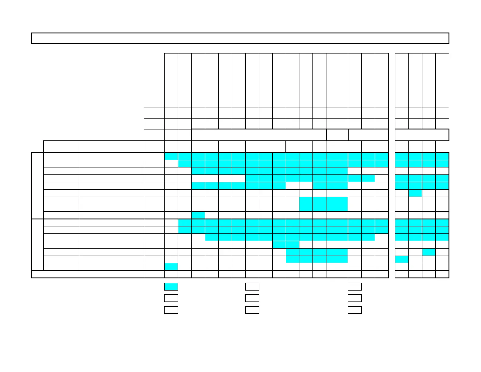
LME-1000
Lockout
Standby, Waiting for Call
Test - Air Pressure Switch
Blower On
D
rive to Prepurge Speed
Test - Air Pressure Switch
Prepurge (Note 2)
D
rive to Ignition Speed
Preignition
Trial for Ignition
Flame Detection
Operation
D
rive to Postpurge Speed
Postpurge (Note 3)
Home Run
Evacuate
Atmospheric Test
Fill
Pressure Test
Phase LOC OFF 21 22 24 22 30 36 38 40 42 44 oP 72 74 10 80 81 82 83
Param. 224 225 226 257 240 234 242 243 244 245
Terminal Description Notes
X3-04.5 Main Voltage
X3-04.1 Safety Loop
X5-03.1 Burner On M
X3-02.1 Air Pressure Switch X M
X5-01.2 Gas Pressure Switch(es)
X9-04.2 Valve Proving Pressure Switch X
X2-02.4 POC
X2-02.3 POC Source X
X6-03.3 Safety Valve X
X2-01.3 Blower X X X X
X4-02.3 Ignition Transformer X X X X X X X X X X X X X X X X X X
X7-04.4 Main Valve V1 X X X X X X X X X X X X X X X
X7-01.3 Main Valve V2 X X X X X X X X X X X X X X X
X2-03.3 Alarm X X X X X X X X X X X X X X X X X X X
S S S S T P P T I I I I O T P T P P P P
Legend :
Energized M
Must be energized by end of phase
I
Ignition speed
Energized or de-energized S
Standby speed
O
X De-energized P
Prepurge/postpurge speed
T
Speed transitioning/modulating
PWM Blower Speed
SHUTDOWN VALVE PROVING
PME71.901A1 Phase Diagram
X
SAFETY
TIME 1
STARTUP
Flame Signal
OUTPUTS
X
X10-05.2
X10-06.1/2
X
Operation - speed
determined by input signal
INPUTS
SCC Inc. Page 14 Section 2

 Loading...
