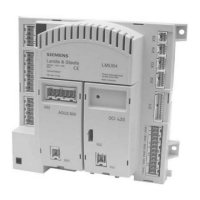
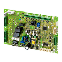
Do you have a question about the Siemens LMU64 Series and is the answer not in the manual?
Describes the full functionality of the LMU..., including safety functions and supervision.
Gas burner control conforming to EN 298 for intermittent operation and integrated boiler/burner control.
Control of AC 230 V fan, ignition load precontrol, adaptive postpurge, load limitation, and flame stabilization.
Parameterization enables changing burner control programs, distinguished by boiler capacity ranges.
Illustrates burner control phases for different capacity ranges (<70 kW, 70-120 kW).
Checks PWM control values and speed parameters for plausibility against other parameters.
Overrides boiler control when max temperature is reached, causing shutdown or forced signal.
Supervises flue gas temperature, reducing output or shutting down the boiler if thresholds are exceeded.
Details faults, functions, operating states, and lockout actions.
Water pressure supervision overrides boiler temperature control, responding to pressure thresholds.
Ensures protection against freezing independently of heat demand, triggering startup if needed.
Uses 2-position control for startup/shutdown signals and implements boiler cycling protection.
Ensures protection when outside temperature drops, activating heating circuit pumps.
Limits maximum flow temperature by stepwise increasing volumetric flow until maximum is reached.
Limits minimum volumetric flow to ensure expected ΔT does not exceed adjusted ΔT.
Details applications for extending heating circuits, external DHW heating, and multiboiler plants.
Calculates boiler setpoint by adding boost to DHW setpoint, with limitations.
Compensation mode depends on plant components, generating 'Compensation variant Bw'.
Describes choices and channels for parameterizing the BMU via PC tool, HMI, or room units.
Diagram illustrating the LMU... system's inputs, outputs, and connections to various components.
Shows LMU... terminal connections for mains, clip-ins, ignition, sensors, and outputs.
Covers general mounting, LMU5x mounting, ignition device, terminals, wiring, and testing.
Lists general technical data including mains voltage, power consumption, degree of protection, and environmental conditions.
Details current, voltage, and cable length specifications for various LMU... connections.
Comprehensive list of parameters for LMU..., categorized by function group.
| Model | LMU64 Series |
|---|---|
| Manufacturer | Siemens |
| Burner control | Single-stage, two-stage, modulating |
| Operating Temperature | -20...+60 °C |
| Relative Humidity | < 95 % r. h. |
| Type of gas | Natural gas, LPG |
| Flame supervision | Ionization probe, UV flame detector |


