89/171
Siemens Building Technologies Basic Documentation LMU54... / LMU64... CC1P7494en
HVAC Products 6 Clip-in function module AGU2.51x 07.11.2002
6 Clip-in function module AGU2.51x
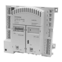
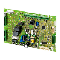
The clip-in function module represents an extension of the LMU... basis in terms of
inputs and outputs. It has 1 input and up to 3 outputs.
All outputs are AC 230 V outputs.
The input of the clip-in function module is a digital or analog input, depending on the
type of module. The analog input can be one of the following:
− Sensor input (NTC, 10 kΩ)
− Voltage input (DC 0...10 V)
− Current input (4...20 mA, 0...20 mA)
Maximum one clip-in module AGU2.51x... can be connected to the LMU5... / LMU6... .
A maximum of 2 clip-in modules (OCI420 / AGU2.500... / AGU2.51x) can be connected.
The outputs of the clip-in function module are used by the LMU... as programmable
outputs. For each of the maximum of 3 outputs on the clip-in module, a function can be
selected via a specific parameter.
The functions are described in chapter «Programmable output of the LMU...».
Assignment of the required functions to the individual outputs of the clip-in function
module is made via parameters «KonfigAusgang1R», «KonfigAusgang2R» and
«KonfigAusgang3R».
The clip-in function module may not be able to handle all 3 available outputs, the reason
being limited power supply.
If, in addition to the clip-in function module, no other clip-in or the mixing valve clip-in
module is connected, all 3 outputs can be handled. If, in addition to the clip-in function
module, an LPB clip-in module is used, only outputs 1 and 2 of the clip-in function
module can be handled.
Functions
General
Note
Outputs
Number of available
outputs

 Loading...


