119/171
Siemens Building Technologies Basic Documentation LMU54... / LMU64... CC1P7494en
HVAC Products 9 Connection diagrams 07.11.2002
9.10 Mounting, electrical installation and service
On the boiler, the unit must be fitted in a housing ensuring degree of protection of
at least IP 40.
Depending on the field of use, more stringent degrees of protection may be
required, which must then be observed.
When mounted, the maximum permissible ambient temperature may not be
exceeded!
The unit is designed for mounting on the burner or in the control panel.
Protection against electric shock hazard must be ensured!
Condensation water may not fall on or get inside the LMU..., neither in operation
nor during service work!
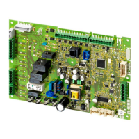
When mounting the printed circuit board on a metal surface, the gap between the
underside of the printed circuit board and the metal surface must be ≥ 12 mm
(conforming to EN 60 335 → minimum 8 mm air path and creeping distance to the
end of the wires or solder fillets).
− The spacers must be made of electrically nonconducting material!
− When using fixing screws made of metal, the diameter of the head must be ≤ 6 mm!
− If the spacers use metal fixing screws on each side, the air path between the screws
must be ≥ 8 mm or solid insulation of 2 mm must be fitted (EN 60 335)!
Electric ignition sparks generate high-frequency energy that can adversely affect radio
and television reception. In that case, the high-voltage cable running to the ignition
electrode acts as a transmitter.
The ignition module integrated in the LMU… is equipped with appropriate filters which
prevent high-frequency energy from being passed from the ignition cable to the other
terminals.
An application-specific test is still required, however, to prove that spacing is adequate.
High-frequency energy also spreads as capacitance and inductance, which means that
it is not bound to cable. This must be considered when laying cables.
The ignition cable must meet the technical specification of the integrated ignition
module. It should be run to the ignition electrode as directly as possible, with no
loops.
It may never be laid parallel or very close to other electrical conductors.
The RAST 2.5 connection area on the narrow side of the unit operates on protective
extra low-voltage.
When making the wiring, the extra low-voltage area must be strictly separated
from other voltage areas to ensure protection against electric shock hazard!
With the RAST5 connectors, the predefined coding must be observed!
Make connections to components only when power is switched off!
Ensure protection against electric shock hazard on unused AC 230 V connection
terminals (RAST5) by fitting dummy plugs!
To isolate the unit from the mains network, use a multipolar switch.
For wiring the bus users, only the cables specified by Siemens may be used!
Mounting (general)
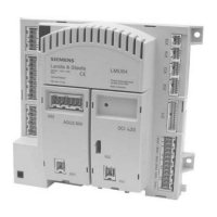
Mounting the LMU5x...
Ignition device
Terminals and wiring

 Loading...


