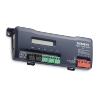
Figure 6: Power Meter Connections.
Completing the Wiring Connections - RS-485,
Voltage Leads and CTs
The FLN cable within electric panels and switchgear should be jacketed, shielded,
twisted triad wire BELDEN 1121A. The jacket insulation rating should be 600V.
DO NOT connect the FLN cable to the field panel yet.
At this time, DO NOT connect the FLN cable to the FLN trunk.
Doing so may damage FLN devices or cause personal injury.
1. Mechanically secure the FLN cable where it enters the cabinet or panel. Remove
the black RS-485 connector from the MD-P1 or MD-P1D Power Meter and wire the
FLN cable to the RS-485 connector. Connect positive (+), and negative (-) wires to
the FLN connector using the daisy-chain method (see Figure 6). Keep length of
exposed wire to a minimum.
2. Connect the COMMON wire to the RS-485 connector (S) terminal (see Figure 6).
3. Tape back one of the FLN cable shields and connect the other shield to the Utility
Panel Ground.
4. If the MD-P1 or MD-P1D is the last FLN device, install the end of line terminator on
the positive (+) and negative (-) terminals. See APOGEE Wiring Guidelines for
Field Panels and Equipment Controllers (125-3002) for additional information.
5. Tape or shrink wrap all FLN wire terminations and insulate any other exposed FLN
wiring. Ensure that insulation complies with local and National Electrical Codes.
 Loading...