Figure 8: Wiring Connections.
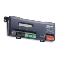
12. Attach the CTs on the power meter's connections labeled CT 1, CT 2 and CT 3.
13. Place the CTs on the phase wires of the load to be monitored and corresponding to
the phase of the voltage leads. The CT labeled CT 1 must be placed on L1 phase
voltage wire; CT 2 must be on the L2 voltage and CT 3 on the L3 voltage. See
Checking Phases for information about the CT LEDs and verifying the CT
installation.
When using the MD-P1 or MD-P1D Model Power Meter with Rogowski Coils (or CTs),
unused CT input(s) should be shorted with a jumper wire if all three coils are not
connected. An unconnected CT input may not show "zero" current due to stray pickup
on the open input.
 Loading...

