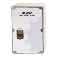
Milltronics MFA 4p
Operating Instructions, 08/2017, A5E33988839_AB
21
The probe and pre-amplifier require no calibration.
Connect the probe, pre-amp, and MFA 4p as shown in the Interconnection (Page 14)
chapter. Connect the MFA 4p to power as shown in the Connection to Power (Page 18)
diagram, and if applicable, as shown for MFA 4p Wiring for Automatic Start Delay (Page 19).
Note
To help the calibration procedure, short N.O. contacts of relays to prevent motor shutdown
(terminals 1
to 2 and/or 4 to 5). This allows the system to run uninterrupted until an operating
Refer to MFA 4p Circuit Board Layout (Page 13)
1. Operate monitored equipment at its normal operating speed.
2. Confirm that Probe LED 1 is pulsing at a regular frequency.
3. Set
fully counter-clockwise (
) to
seconds.
1. Set switch
to
.
2. Set
switch
to
position.
3. Turn
potentiometer fully clockwise
to
.
4. Determine incoming pulse rate by slowly turning
potentiometer
until relay LED
2 goes on. As the MFA 4p requires 2 pulses within range before energizing relays, low
applications (e.g.
) may require stepping of potentiometer at appropriate time
intervals.
5. If no response is obtained when you set the
potentiometer to
(below this stability
suffers), reset potentiometer fully
, set switch
to
and then
if required,
and repeat step 4.
6. When Relay LED 2 goes on, indicating the incoming pulse rate, turn potentiometer
slightly past this point to obtain an operating setpoint that allows for normal fluctuations
due to load and voltage variations. For 50 % of full speed, set potentiometer (and
if
required) to halfway between incoming pulse rate of normal speed and
ppm.
7. Set
by adjusting potentiometer so that equipment being monitored can attain
normal operating speed before LED 2 can turn off.