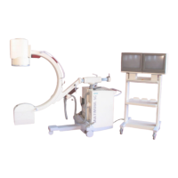
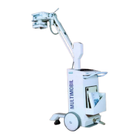
Service Manual
Service Instructions
Siemens Ltd. Med Division India Version 4.0
Page 19 of 48
3.2.2 Checking the fuses
Open the front cover of the control unit.
Loosen the Fuse carrier, which are mounted on the transformer bracket of the
control unit and check the continuity of fuse link. If fuse link has responded for
overcurrent replace the Fuse Link.
3.2.3 Checking the LEDs on D801
F1 6AT Filament Inverter supply.
F2 1AT SMPS supply
F3 2.5AT Rotating Anode supply .
F4 2.5AT 24V Ac supply for Control ckt.
F5 10AT Collimator supply
F6 0.8 AT DC-DC Conv. ckt.
F7 1.6AT 220V AC supply for contactors.
Standby mode
On D801 the following LED’s are illuminated
V30 Supply for SMPS
V31 Supply for Filament Inverter.
V32 Supply for Rotating Anode ckt
V35 12V AC Supply for Collimator
V36 +VP supply
V50 24V DC on D801
V23&V24 DC supply for filament inverter
3.3 Checking the Control Voltages
In the standby state of the Unit,measure the voltages DC at X15 connector of D915
PCB.
Pin
No.
Signal Name Input/Output max. permissible
voltage/current
1 Dgnd Input 0V
2 -nc- -nc- -
3 Dgnd Input 0V
4 DC supply Input + 5V
5 DC supply Input +15V
6 Agnd Input 0V
7 DC supply Input -15V
- nc - = No Connection

 Loading...