For more information about the DF8000 Input/Output modules, including
installation details, see documents
DF8000 Datasheet (document
no.A6V10081184)
and
DF8000 ICC (document no.A6V10081388)
3.2 NK823x hardware
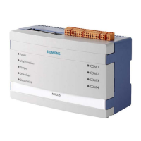
The NK823x is composed of an electronic board (with optional plug-ins) installed in
a compact and robust plastic box.
Note: NK823x units with build state up to 04 are equipped with the NKM8001-A1
mainboard that do not support locally connected DF8000 I/O modules.
Instead, NK823x units with build state 10 or higher are equipped with the
NKM8001-A2 mainboard that can support up to 4 locally connected I/O modules.
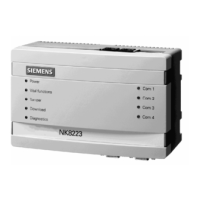
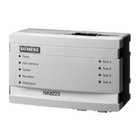
NK823x Ethernet port unit (NK8235 in this example)
3.2.1 Front panel
The front panel houses 9 LED’s.
Left Side LEDs
The five LEDs on the left side are from top to bottom:
Power (green LED)
Power (hardware – controlled).
Vital functions (green LED)
Software vitality:
⚫
Blinking (1 flash)
: core software running.
⚫
Blinking (2 flashes)
: core software running and logging function active.
Tamper (bi-color LED)
Unit tamper:
⚫
Red
means tamper alarm (hardware controlled).
⚫
Green
means tamper disabled (from management station).
Download (red LED)
Network diagnostics:
⚫
Off
: status OK.
⚫
Blinking (1 flash)
: missing identification from NS8xxx.
⚫
Blinking (2 flashes)
: not used.
⚫
Blinking (3 flashes)
: FTP channel open (default mode; for switch settings see
Internal DIP Switches
.

 Loading...


