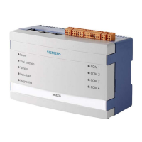
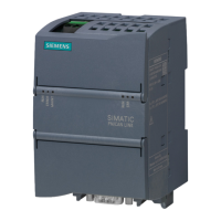
NE8001 housing solution for NK823x
5.1.2 NE8001 hardware installation
The cabinet is typically wall-mounted. A proper support must be provided for the
maximum weight (see Technical data on the NK8000 datasheet). Four supporting
screws or hooks (min. 10 mm) are required.
Supporting wall must not be composed of inflammable material.
Cabinet installation
The VAC power supply wires (1.5 mm
2
) should be connected as illustrated in
Figure
VAC power connection
.
Careful attention should be paid to the correct connections of VAC power lines.
Ground
Phase
Neutral
Input VAC
1.5 mm
2
wires
VAC power connection
Wires pass through 20 mm (cut-out) holes at the top of the cabinet (see Figure
Top
view of NE8001 cabinet
), and continue behind the cabinet to pass through the rear-
side cavity to the entrance hole (see Figure
Wiring (1) – Front view of cabinet
(arrow indicates cut-out holes)
and Figure
Wiring (2) – Entrance hole indicated by

 Loading...


