Fail-Safe Modules
7.5 4/8 F-DI DC24V PROFIsafe Digital Electronic Module
ET 200S Distributed I/O System - Fail-Safe Modules
126 Installation and Operating Manual, 08/2008, A5E00103686-07
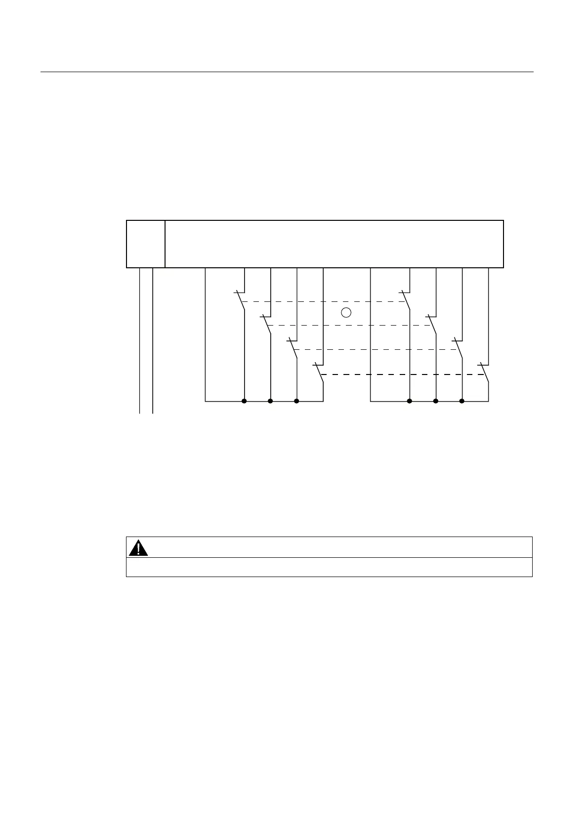
Wiring Diagram for Application 3.1 - Connecting a Two-Channel Sensor to Two Channels
A 2-channel sensor is connected to two inputs of the F-module for each process signal (1oo2
evaluation).
Wiring diagram of the connection of two single-channel sensors to two channels. In this
case, the same process variable is acquired with two mechanically separate sensors.
The wiring is carried out on the appropriate terminal module.
)',
/ 0 ', ' , ', ' , ', ', ' , ',9V 9V
/ 0
6
6
6
6
30(
① Encoder contacts are coupled mechanically
Figure 7-29 Wiring diagram EM 4/8 F-DI DC24V - a 2-channel sensor connected via two channels,
internal sensor supply
Alternatively, two one-channel sensors can be connected via two channels (see figure
"Wiring diagram EM4/8 F-DI DC24V - two one-channel sensors connected via two channels,
internal sensor supply"
). In this case, the same process variable is acquired with two
mechanically separate sensors.
WARNING
To achieve SIL3/Category 4/PLe using this wiring, you must use a suitably qualified sensor.
Assignable Parameters for Application 3.1
Set the "sensor evaluation" to "1oo2 evaluation" at the corresponding input, and "2-channel
equivalent" at the "Type of sensor interconnection" parameter. Activate the "short-circuit test"
parameter and set "internal" at the "sensor supply" parameter.
 Loading...
