Fail-Safe Modules
7.5 4/8 F-DI DC24V PROFIsafe Digital Electronic Module
ET 200S Distributed I/O System - Fail-Safe Modules
Installation and Operating Manual, 08/2008, A5E00103686-07
127
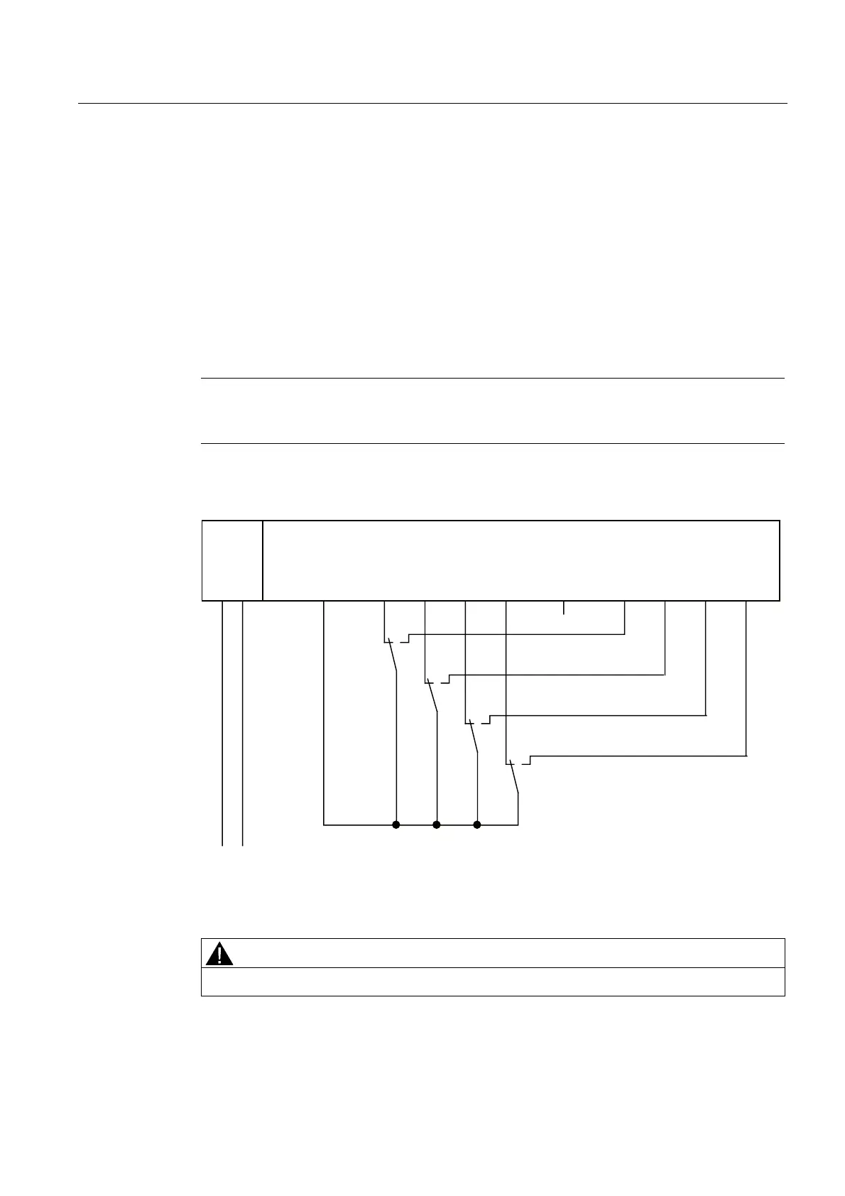
Wiring Diagram for Application 3.2 - Connecting a Nonequivalent Sensor to Two Nonequivalent
Channels
4 process signals can be connected to an EM 4/8 F-DI DC24V PROFIsafe. A sensor is
nonequivalently connected via 2 channels to two inputs of the F-module for each process
signal (1oo2 evaluation).
Alternatively, two one-channel sensors can be connected via two channels (see figure
"Wiring diagram EM 4/8 F-DI DC24V - two one-channel sensors connected via two channels
nonequivalently, internal sensor supply"). In this case, the same process variable is acquired
with two mechanically separate sensors.
The left-hand channels on the F-module (DI0 through DI3) supply the wanted signals. If no
faults are detected, these signals will be available in the I/O area for inputs on the F-CPU.
Note
You must use the internal sensor supply Vs1 to supply voltage to the sensor. Connection to
Vs2 is not possible.
The wiring is carried out on the appropriate terminal module.
)',
/ 0 ', ', ', ', ', ', ', ',9V 9V
/ 0
6
6
6
6
30(
7KHOHIWKDQGFKDQQHOVRQWKH)PRGXOHVXSSO\WKHZDQWHGVLJQDOV
Figure 7-30 Wiring diagram EM 4/8 F-DI DC24V - a nonequivalent sensor connected via two
channels non-equivalently, internal sensor supply
WARNING
To achieve SIL3/Category 4/PLe using this wiring, you must use a suitably qualified sensor.
 Loading...
