Fail-Safe Modules
7.5 4/8 F-DI DC24V PROFIsafe Digital Electronic Module
ET 200S Distributed I/O System - Fail-Safe Modules
108 Installation and Operating Manual, 08/2008, A5E00103686-07
7.5.3 Wiring of the EM 4/8 F-DI DC24V PROFIsafe
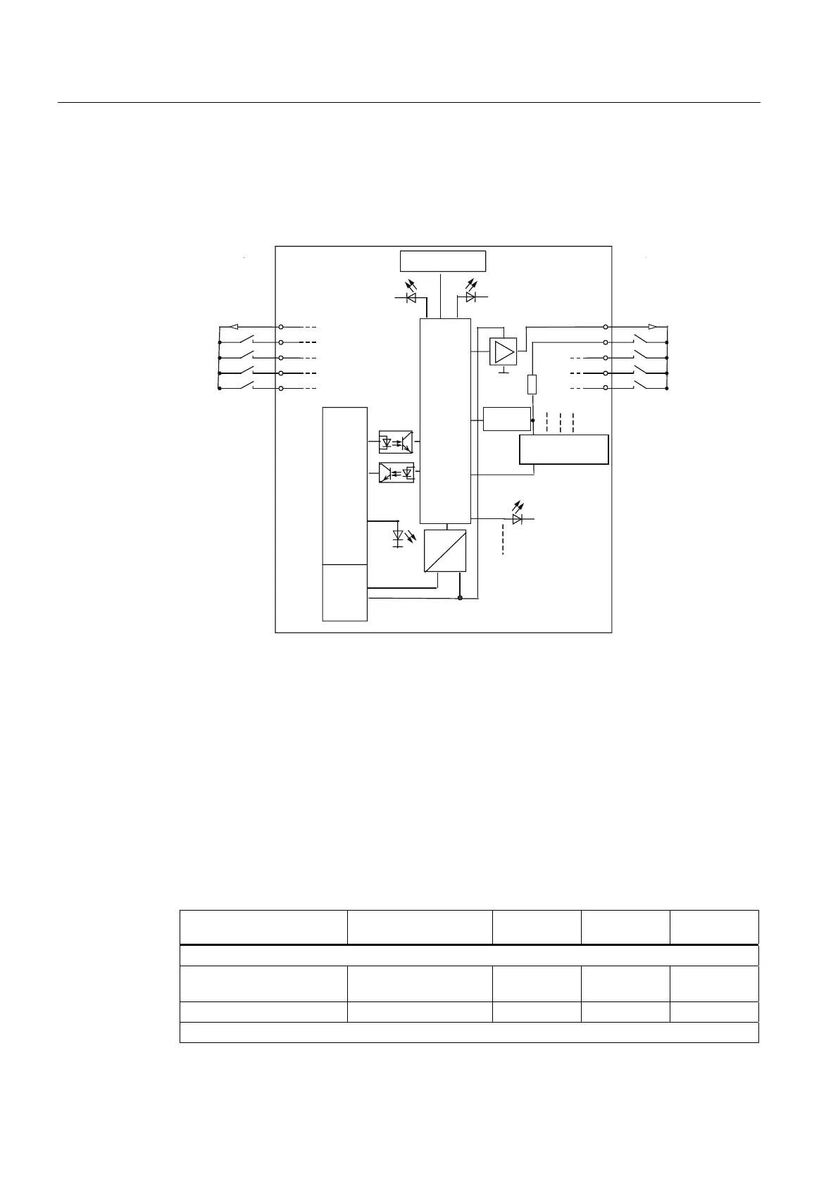
Block diagram
9
0
6)
0
9V
9V
3
3
0
0
0
9
9V)9V)
7KHQRWDWLRQRIWKH12FRQWDFWFRUUHVSRQGVWRWKHPRGXOHLQVFULSWLRQ+RZHYHUWKHHQFRGHU
FRQWDFWVPXVWEH1&FRQWDFWVLQJHQHUDOEHFDXVHRIWKHVDIHVWDWHRIWKHSURFHVVYDULDEOHV
$GGUHVVVZLWFK
)LOWHUORJLF
7HVWLQJ
6WDWXV
%DFNSODQHEXVLQWHUIDFH
3URFHVVLQJORJLF
Figure 7-17 Block Diagram of EM 4/8 F-DI DC24V PROFIsafe
7.5.4 Parameters of the EM 4/8 F-DI DC24V PROFIsafe
Parameters in
STEP 7
The table below lists the parameters that can be set for the EM 4/8 F-DI DC24V PROFIsafe.
Table 7- 17 Parameters of the EM 4/8 F-DI DC24V PROFIsafe
Parameter Range Default Type of
Parameter
Effective
Range
F-Parameters:
F_destination_address 1 to 1022 are assigned
by
STEP 7
Static Module
F monitoring time 10 to 10,000 ms 150 ms Static Module
Module Parameters:
 Loading...
