Fail-Safe Modules
7.5 4/8 F-DI DC24V PROFIsafe Digital Electronic Module
ET 200S Distributed I/O System - Fail-Safe Modules
Installation and Operating Manual, 08/2008, A5E00103686-07
115
7.5.6 Application 1: SIL2/Category 3/PLd safety mode
Sensor supply
The EM 4/8 F-DI DC24V PROFIsafe provides sensor supply Vs1 for Inputs 0 to 3 and sensor
supply Vs2 for Inputs 4 to 7. The sensor supply can be powered internally or externally.
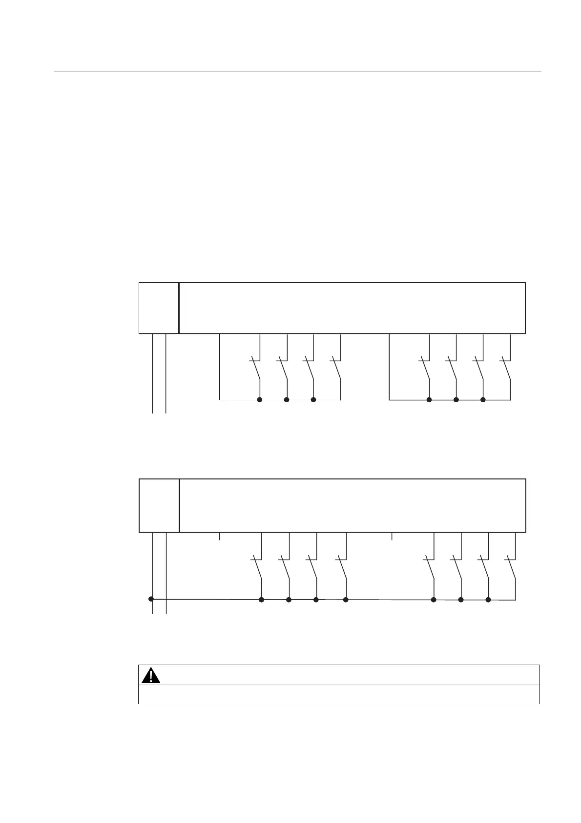
Wiring Diagram for Application 1 – Connecting One Sensor to One Channel
One sensor is connected to one channel (1oo1 evaluation) for each process signal.
The wiring is carried out on the appropriate terminal module.
)',
/0 ',',',', ',',',',9V 9V
/ 0
30(
6 6 6 6 6 6
6 6
Figure 7-19 Wiring diagram EM 4/8 F-DI DC24V PROFIsafe - one sensor connected via one
channel, internal sensor supply
)',
/ 0 ', ', ', ' , ', ', ' , ' , 9V 9V
/ 0
30(
6666 6666
Figure 7-20 Wiring diagram EM 4/8 F-DI DC24V PROFIsafe - one sensor connected via one
channel, internal sensor supply
WARNING
To achieve SIL2/Category 3/PLd using this wiring, you must use a suitably qualified sensor.
 Loading...
