Fail-Safe Modules
7.5 4/8 F-DI DC24V PROFIsafe Digital Electronic Module
ET 200S Distributed I/O System - Fail-Safe Modules
128 Installation and Operating Manual, 08/2008, A5E00103686-07
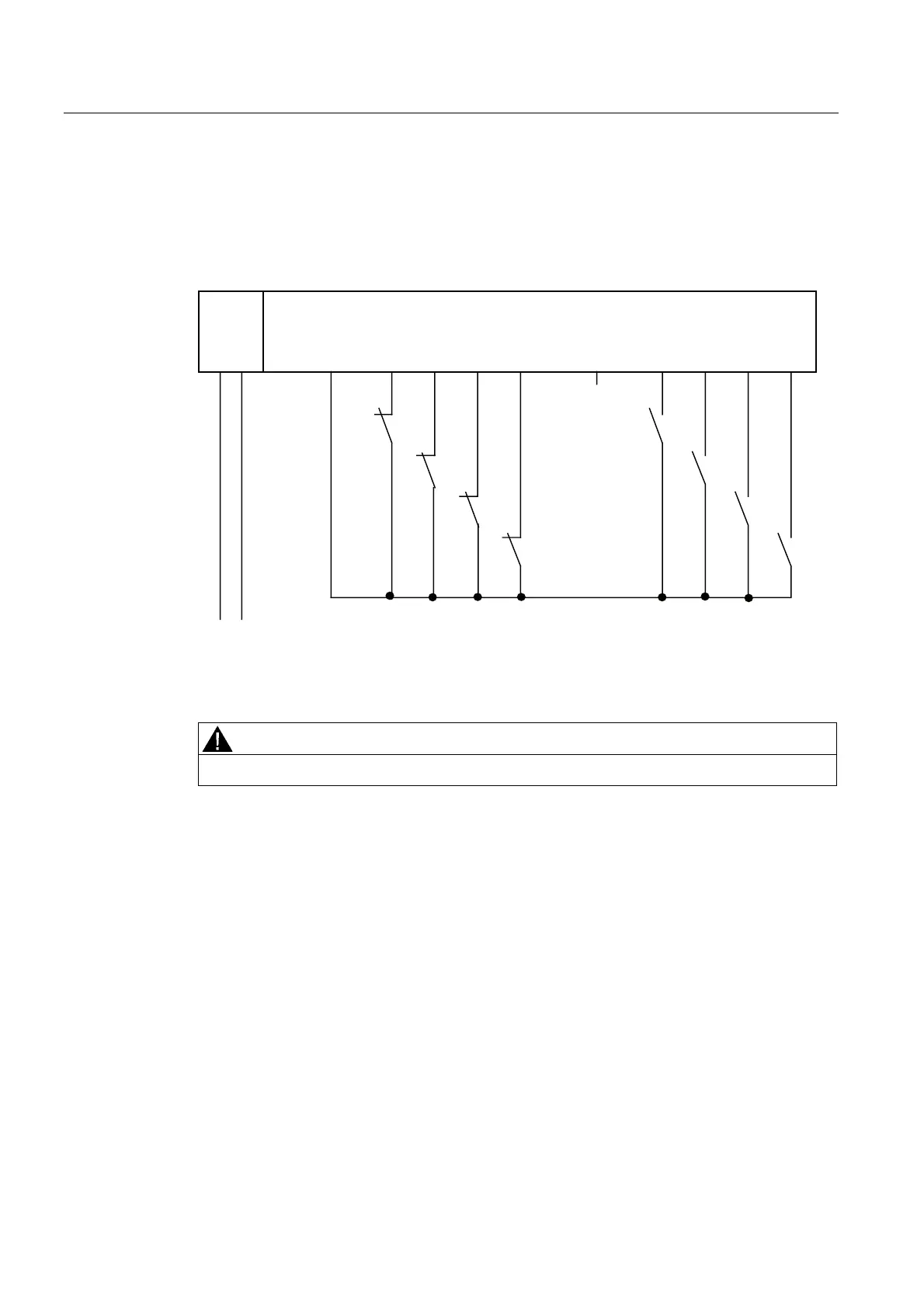
Wiring Diagram for Application 3.2 – Connecting Two Single-Channel Sensors Nonequivalently via
Two Channels
The left-hand channels on the F-module (DI0 through DI3) supply the wanted signals. If no
faults are detected, these signals will be available in the I/O area for inputs on the F-CPU.
)',
/ 0
', ', ', ', ', ', ', ',9V 9V
/ 0
6
6
6
6
30(
7KHOHIWKDQGFKDQQHOVRQWKH)PRGXOHVXSSO\WKHZDQWHGVLJQDOV
Figure 7-31 Wiring diagram EM 4/8 F-DI DC24V - two 1-channel sensors connected via two
channels, internal sensor supply
WARNING
To achieve SIL3/Category 4/PLe using this wiring, you must use a suitably qualified sensor.
Assignable Parameters for Application 3.2
Set the "sensor evaluation" to "1oo2 evaluation" at the corresponding input, and "2-channel
equivalent" at the "Type of sensor interconnection" parameter. Activate the "short-circuit test"
parameter and set "internal" at the "sensor supply" parameter.
 Loading...
