Fail-Safe Modules
7.6 EM 4 F-DI/3 F-DO DC24V PROFIsafe digital electronic module
ET 200S Distributed I/O System - Fail-Safe Modules
146 Installation and Operating Manual, 08/2008, A5E00103686-07
Sensor Requirements
Please note the information in section
"Requirements for Sensors and Actuators"
when using
sensors for safety-related applications.
Assigning Inputs to Each Other
The EM 4 F-DI/3 F-DO DC24V PROFIsafe has 8 fail-safe inputs, DI 0 through DI 7 (SIL2).
Each pair of these inputs can be operated as one input (SIL2). The following assignment
applies:
● DI0 with DI4
● DI1 with DI5
● DI2 with DI6
● DI3 with DI7
Sensor Supply
The 4 F-DI/3 F-DO DC24V PROFIsafe EM makes available the VS sensor supply for the
Inputs 0 to 7.
The sensors can be powered internally or externally.
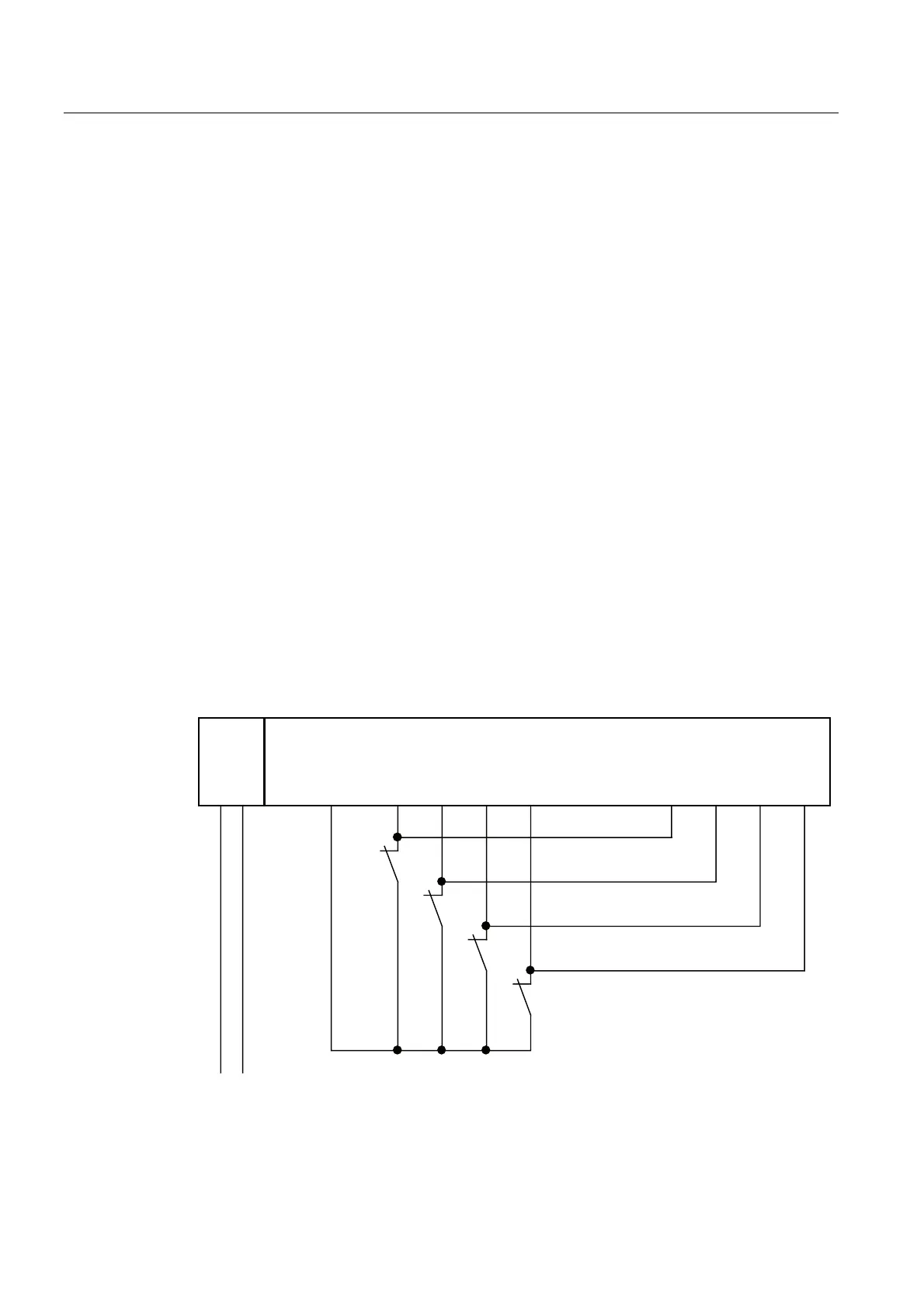
Application 1.1: Wiring diagram for connecting single-channel sensor to two inputs
Single-channel connection of a sensor to two inputs of the F-module for each process signal
(1oo2 evaluation).
The wiring is carried out on the appropriate terminal module.
)',)'2
30(
/ 0 96 ', ', ', ', ', ', ', ',
/
0
6
6
6
6
Figure 7-37 Wiring diagram EM 4 F-DI/3 F-DO DC24V - one sensor connected via one channel to
two inputs, internal sensor supply
 Loading...
