Address Assignment and Installation
3.1 Address assignments in the F-CPU
ET 200S Distributed I/O System - Fail-Safe Modules
28 Installation and Operating Manual, 08/2008, A5E00103686-07
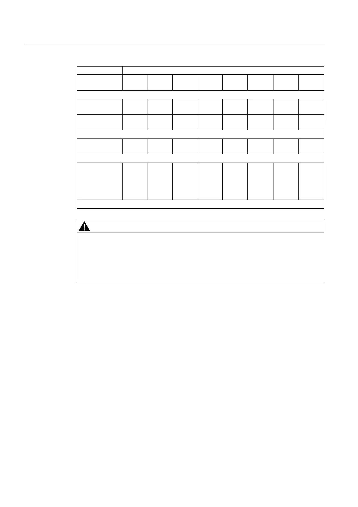
Occupied Bits in F-CPU per F-Module:
x + 0 Channel
7
Channel
6
Channel
5
Channel
4
Channel
3
Channel
2
Channel
1
Channel
0
4 F-DI/3 F-DO DC24V PROFIsafe:
x + 0 (inputs) — — — — Channel
3
Channel
2
Channel
1
Channel
0
x + 0 (outputs) — — — — — Channel
2
Channel
1
Channel
0
4 F-DO DC24V/2A PROFIsafe:
x + 0 — — — — Channel
3
Channel
2
Channel
1
Channel
0
1 F-RO DC24V/AC24..230V/5A:
x + 0 — — — — — — 0 Channel
0
(Readba
ck
channel)
x = Module start address
WARNING
You may only access the addresses occupied by useful data. The other address ranges
occupied by the F-modules are assigned for functions including safety-related
communication between the F-modules and F-CPU in accordance with PROFIsafe.
With the 1oo2 evaluation of sensors, only the less significant channel of the channels that
are grouped as a result of the 1oo2 sensor evaluation can be accessed in the safety
program.
Additional Information
Detailed information about fail-safe I/O access can be found in the
S7 Distributed Safety,
Configuring and Programming
manual or the
S7 F/FH Systems, Configuring and
Programming
manual.
 Loading...
