Fail-Safe Modules
7.2 PM-E F pm DC24V PROFIsafe Power Module
ET 200S Distributed I/O System - Fail-Safe Modules
Installation and Operating Manual, 08/2008, A5E00103686-07
73
WARNING
The controlled actuator can no longer be switched off when there is a cross circuit
between the P and M-switches of the output. To avoid cross circuits between the P and
M-switches of a fail-safe digital output, you should always wire the relay connection to
the P and M-switches separately, in order to prevent any cross-circuits (for example with
separately-sheathed cables or using separate cable ducts).
Note
The PM-E F pm DC24V PROFIsafe carries out a bit pattern test every 15 minutes or so.
The module then sends an impulse for max. 4 ms. This test is executed deferred between
P and M-switches, so that the actuator is not switched on. This impulse may cause the
corresponding relay to tighten, which may reduce its service life.
We therefore recommend adhering to the wiring scheme detailed below.
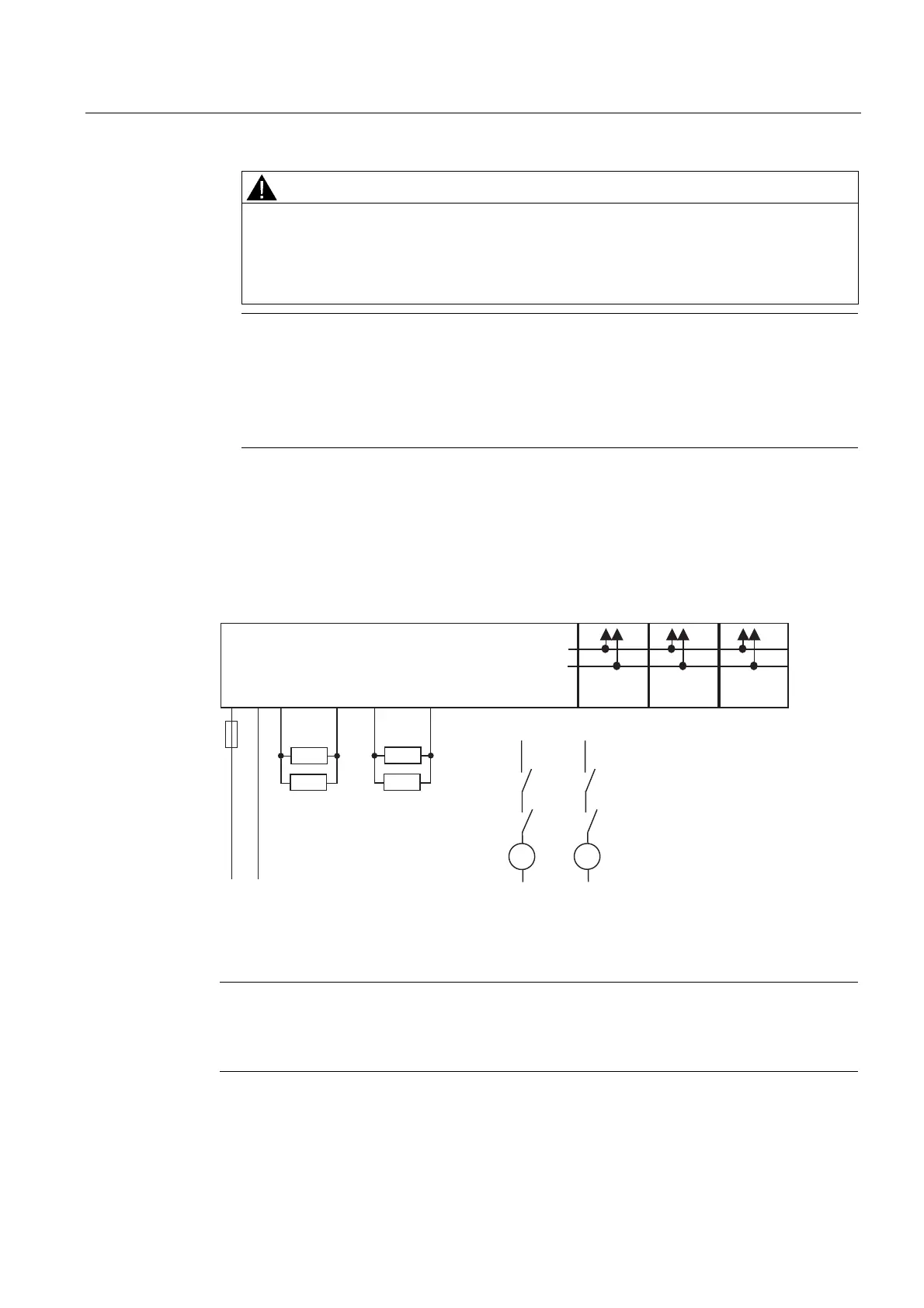
Application 3: Wiring two loads in parallel to each digital output
Avoiding / Managing Cross Circuits:
To protect against cross circuits between P and M-switches in fail-safe digital outputs, we
recommend the following wiring scheme:
/ 0
/ 0
'2
0
'2
3
'2
0
'2
3
30
33
(0'2 (0'2 (0'2
.
.
.
.
.
.
.
.
0
0
3
'2
3
3
'2
0
'2
3
'2
3
'2
3
'2
0
'2
0
'2
0
30()SP'&9
Figure 7-8 Wiring diagram for each of two relays parallel on DO 0 and DO 1 of the PM-
E F pm DC24V PROFIsafe
Note
With parallel connection of two relays to one digital output (as shown above), the "wire
break" fault is only detected if the wire break disconnects both relays from P or M. This
diagnosis is not safety-related.
 Loading...
