Chapter 2
Installing the Device
RUGGEDCOM RS910
Installation Guide
10 Connecting Low DC Power
2. Connect the negative wire from the power source to the negative/neutral (-/N) terminal on the terminal block.
3. Using a braided wire or other appropriate grounding wire, connect the surge ground terminal to the chassis
ground connection. The surge ground terminal is used as the ground conductor for all surge and transient
suppression circuitry internal to the unit.
4. Connect the ground terminal on the power source to the chassis ground terminal on the device.
Section2.3.2
Connecting Low DC Power
RUGGEDCOM RS910's equipped with 24 or 48 V power supply inputs feature reverse polarity protection and dual
power supply inputs allowing the device to accept redundant connections to a single DC power supply.
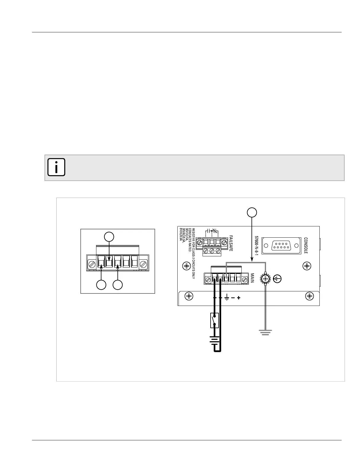
To connect a low DC power supply to the device, do the following:
NOTE
Torque all terminal connections to 0.6 N·m (5 lbf-in).
1. Connect the positive wire from the power source to the positive terminal on the terminal block.
Figure5:Terminal Block Wiring - Single DC Power Supply Inputs
1.Positive Terminal 2.Negative Terminal 3.Surge Ground Terminal 4.Braided Ground Cable
2. Connect the negative wire from the power source to the negative terminal on the terminal block.
3. [Optional] If a redundant connection is required, repeat steps Step 1 and Step 2 to connect the secondary
power inputs.

 Loading...