RUGGEDCOM RS910
Installation Guide
Chapter 2
Installing the Device
Connecting the Failsafe Alarm Relay 11
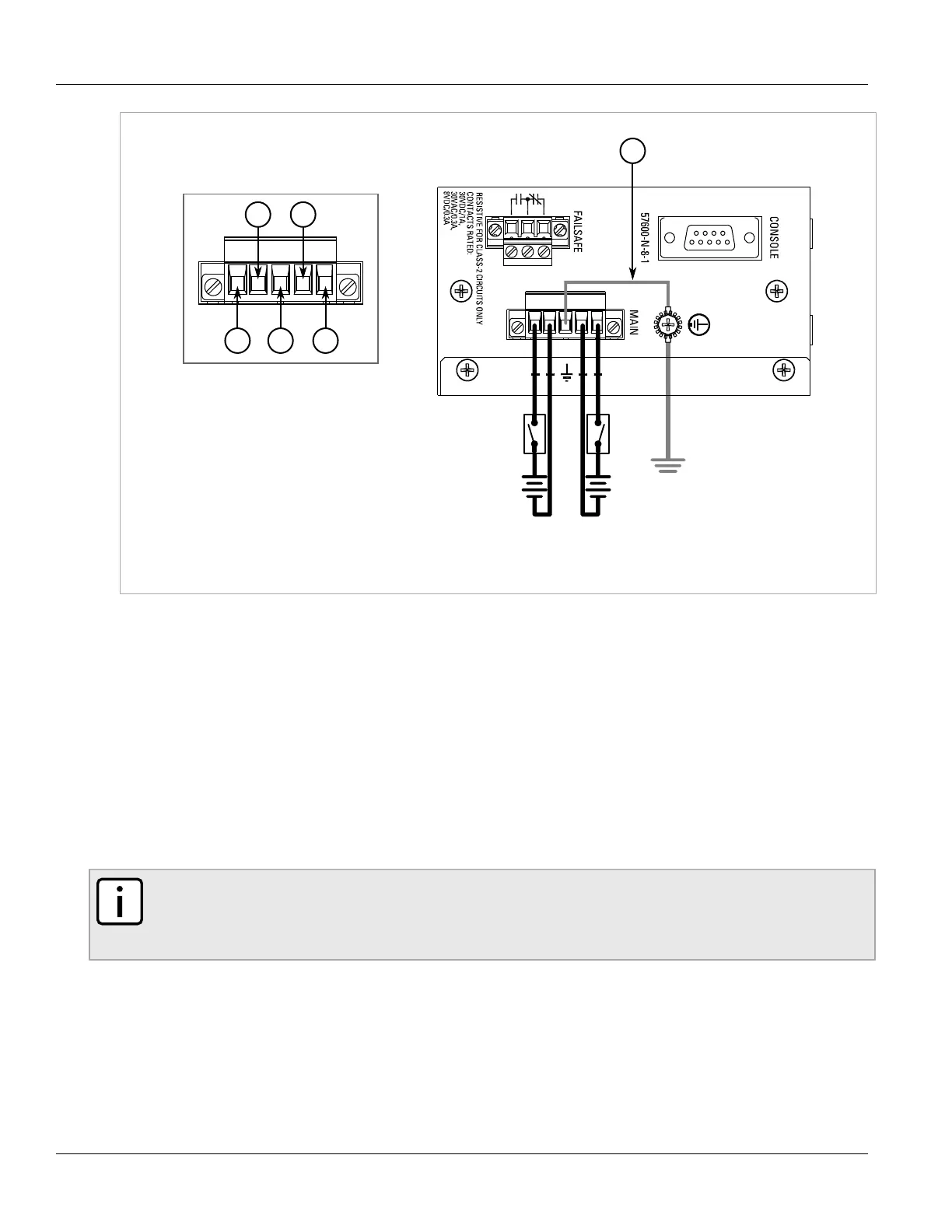
Figure6:Terminal Block Wiring - Dual DC Power Supply Inputs
1.Positive Terminal 2.Negative Terminal 3.Surge Ground Terminal 4.Braided Ground Cable
4. Using a braided wire or other appropriate grounding wire, connect the surge ground terminal to the chassis
ground connection. The surge ground terminal is used as the ground conductor for all surge and transient
suppression circuitry internal to the unit.
5. Connect the ground terminal on the power source to the chassis ground terminal on the device.
Section2.4
Connecting the Failsafe Alarm Relay
The failsafe relay can be configured to latch based on alarm conditions. The NO (Normally Open) contact is closed
when the unit is powered and there are no active alarms. If the device is not powered or if an active alarm is
configured, the relay opens the NO contact and closes the NC (Normally Closed) contact.
NOTE
Control of the failsafe relay output is configurable through ROS. One common application for this relay
is to signal an alarm if a power failure occurs. For more information, refer to the ROS User Guide for
the RUGGEDCOM RS910.
The following shows the proper relay connections.

 Loading...