Chapter 3
Communication Ports
RUGGEDCOM RS910
Installation Guide
18 Serial Ports
Section3.3
Serial Ports
The RUGGEDCOM RS910 supports DB9, RJ-45 and ST (Straight Tip) fiber serial ports, all of which can be run in
RS232, RS485 or RS422 mode.
NOTE
On power-up, all serial ports default to RS485 mode. Each port can be individually set to RS232, RS485
or RS422 mode through RUGGEDCOM ROS. For more information, refer to the RUGGEDCOM ROS User
Guide for the RUGGEDCOM RS910.
LED
All serial ports feature an LED that indicates the current state of the port.
State Description
Green Link activity detected
Off No link detected
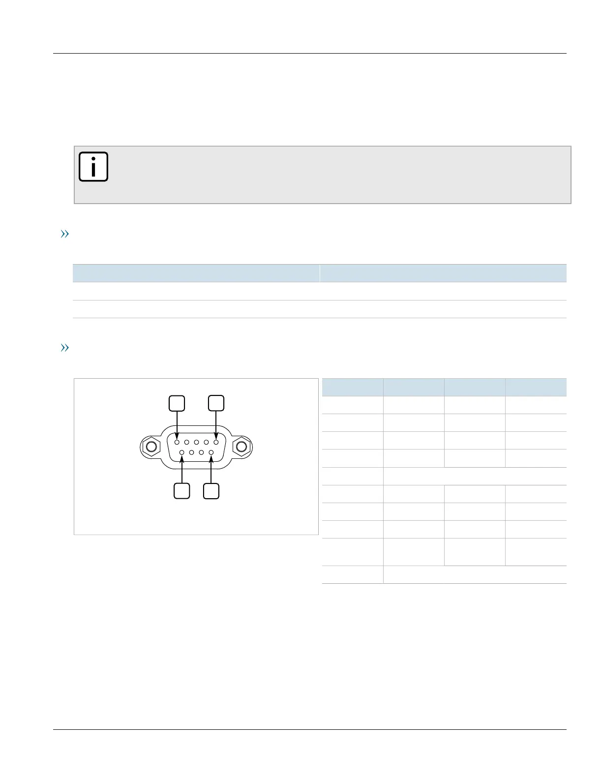
Pin-Out
The following are the pin-outs for the DB9, RJ-45 and SC connectors:
Figure16:Serial DB9 Port
Pin
a
RS232 Mode RS485 Mode RS422 Mode
1
b
DCD
2 TX TX/RX+ TX+
3 RX RX+
4
b
DTR
5 Common (Isolated Ground)
c
6
b
DSR RX-
7
d
CTS
e
TX/RX- TX-
8
d
RTS
e
9 RI (No
Connection)
Shield Chassis Ground
a
No internal termination is provided.
b
Connected internally.
c
The Common terminal is isolated. However, there is transient voltage protection circuitry between the Common terminal and chassis ground.
d
Cnnected internally.
e
In RS232 mode, this pin enters a high impedance state. A DTE that asserts RTS will see CTS asserted, although the device will not perform hardware flow control.

 Loading...