14/57 CC1B7865en 05.12.2002 HVAC Products
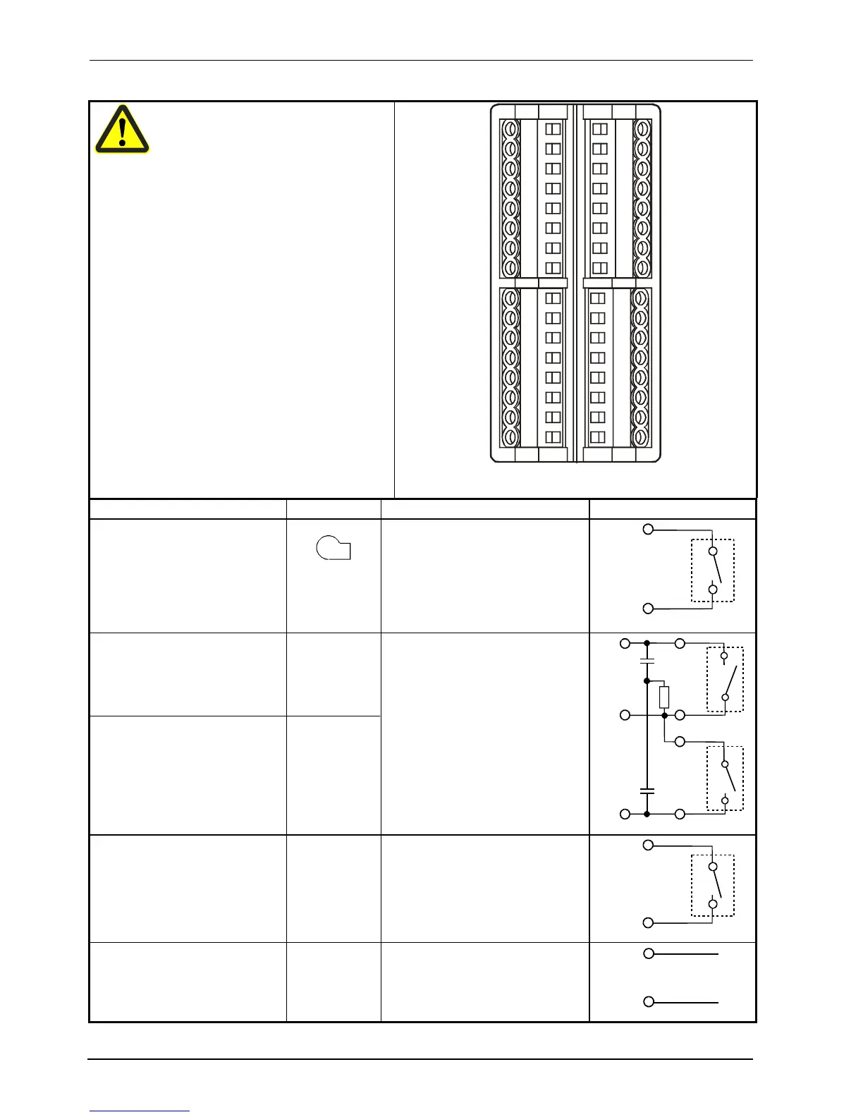
4. Electrical connections
Electrical connections may only be made
by qualified personnel!
7865z07/1199
X1+
X1-
G-
G+
GND
D1
D2
I1
CB
CG
CA
TE
L1
N
Y2
M1
U1
G1+
XB6
M6
XU6
B9
M9
Q
Y1
Q13
Q14
Q63
Q64
Outputs Display LED Terminal no. Connection diagram
Relay 1: Release of burner
Can be used as a thermal reset
limit thermostat to DIN 3440
Contact protection:
Varistor S07K275
Q14 pole
Q13 N.O. contact
Q14
P
S
Q13
7865a11/1199
Relay 2: Actuating device opens
Contact protection:
RC unit
Relay 3: Actuating device closes
Contact protection:
RC unit
=
>
Y1 N.O. contact
Q common pole
Y2 N.O. contact
P
S
Y1
Q
Y2
S
P
7865a16/1099
Relay 4: Limit comparator
Contact protection:
Varistor S07K275
K6 Q64 pole
Q63 N.O. contact
Q64
P
S
Q63
7865a15/1099
Analog output (optional)
DC 0 (4)...20 mA, 0 (2)...10 V
X1+
X1-
X1+
X1-
+
-
7865a17/1099
4.3 Assignment of terminals
 Loading...


