Description of the device
2.7 LED display
SCALANCE XM-400
Operating Instructions, 05/2014, C79000-G8976-C306-03
23
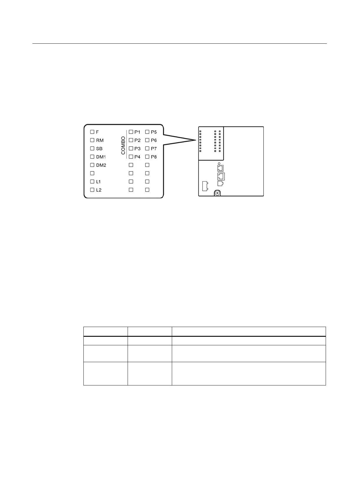
The following figure shows the arrangement of the LEDs.
LED for displaying the fault/error status
LED for displaying the "redundancy manager" function
LED for displaying the "standby" function
LEDs for displaying the display mode
LEDs for displaying the power supply
LEDs for displaying the port status *)
Indicates that the LEDs belong to combo ports
*
)
The number of port LEDs depends on the device.
The "RM" LED indicates whether or not the device is a redundancy manager and whether or
not the ring is operating free of error.
The device is not a redundancy manager.
Green On The device is a redundancy manager.
The ring is working without problems, monitoring is activated.
Green Flashing The device is a redundancy manager.
An interruption has been detected on the ring and the device
 Loading...