Description of the device
2.7 LED display
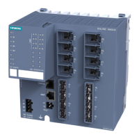
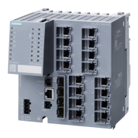
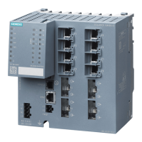
SCALANCE XM-400
26 Operating Instructions, 05/2014, C79000-G8976-C306-03
The "L1" and "L2" LEDs indicate the current range of the power supply at connectors L1 and
L2.
The meaning of the "L1" and "L2" LEDs depends on the set display mode, see section
"LEDs "DM1" and "DM2" (Page 25)".
Meaning in display modes A, B, C and E
In display modes A, B, C and E, from the "L1" and "L2" LEDs you can see whether the
power supply is higher or lower than 17 V.
Power supply lower than 17 V
Power supply higher than 17 V
Meaning in display mode D
In display mode D, the "L1" and "L2" LEDs indicate whether the power supply is monitored.
- Off Power supply is not monitored.
If the power supply falls below 17 V, the signaling contact does
Green On Power supply is monitored.
If the power supply falls below 17 V, the signaling contact
 Loading...