Connecting up
4.3 Power supply
SCALANCE XM-400
48 Operating Instructions, 05/2014, C79000-G8976-C306-03
Information on the power supply
● The "L1" and "L2" LEDs indicate the current range of the power supply, see the section
"LEDs "L1" and "L2" (Page 26)".
● The power supply is connected using a 4-pin plug-in terminal block (spring-loaded
terminal). The terminal block ships with the device and can also be ordered as a spare
part.
● The power supply can be connected redundantly. Both inputs are isolated. There is no
distribution of load. When a redundant power supply is used, the power supply unit with
the higher output voltage supplies the SCALANCE XM-400 alone.
● The power supply is connected over a high resistance with the enclosure to allow an
ungrounded set up. The two power inputs are non-floating.
● To wire up the power connector, use a copper cable of category 18-12 AWG or cable with
a cross-section of 0.75 to 2.5 mm².
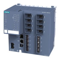
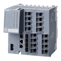
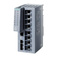
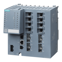
Figure 4-1 Position of the power supply on the SCALANCE XM-400 and the assignment of the
terminal block
L1+ L1+ 24 VDC
 Loading...
