2 Hardware setup
The aim of the following application example is to establish communication
between 2 PCs. Diagnostics need to be checked with a ping command from PC 1
to PC 2.
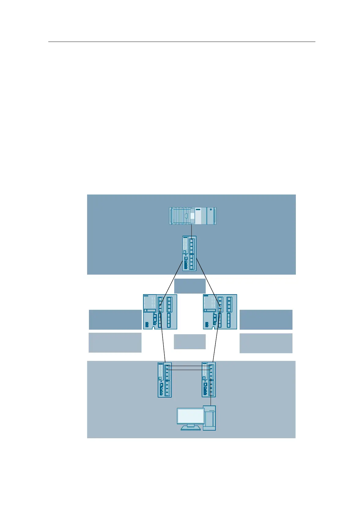
The following figures show the physical network structure.
The document explains 2 different hardware configurations:
• Hardware configuration with XM408-8C (no firewall)
• Hardware configuration with S615 (with firewall)
The Figure below shows the hardware setup with the SCALANCE XM408-8C.
Figure 2-1
PC 1
IP address: 192.168.10.20
Subnet mask: 255.255.255.0
Gateway: 192.168.10.1
SCALANCE XC 206
IP address: 192.168.10.10
Subnet mask: 255.255.255.0
Gateway: 192.168.10.1
VLAN10/ subnet – B 192.168.10.0/24
Virtual router
VRRP Instance 10
IP: 192.168.10.1
SCALANCE XM408-8C (Master)
Port 1.1: Interface VLAN 1
Function: Configuration
IP address: 192.168.1.2
Subnet mask: 255.255.255.0
Port 1.3: Interface VLAN 10
Function: Server room
IP address: 192.168.10.2
Subnet mask: 255.255.255.0
Port 1.4: Interface VLAN 20
Function: Cell
IP address: 192.168.20.2
Subnet mask: 255.255.255.0
SCALANCE XM408-8C (Backup)
Port 1.1: Interface VLAN 1
Function: Configuration
IP address: 192.168.1.3
Subnet mask: 255.255.255.0
Port 1.3: Interface VLAN 10
Function: Server room
IP address: 192.168.10.3
Subnet mask: 255.255.255.0
Port 1.4: Interface VLAN 20
Function: Cell
IP address: 192.168.20.3
Subnet mask: 255.255.255.0
Virtual router
VRRP Instance 20
IP: 192.168.20.1
PC 2
IP address: 192.168.20.20
Subnet mask: 255.255.255.0
Gateway: 192.168.20.1
SCALANCE XC 206
IP address: 192.168.20.11
Subnet mask: 255.255.255.0
Gateway: 192.168.20.1
VLAN20/ subnet – A 192.168.20.0/24
SCALANCE XC 206
IP address: 192.168.20.10
Subnet mask: 255.255.255.0
Gateway: 192.168.20.1
 Loading...