3-6
C7-621 / C7-621 AS-i Control Systems
C79000-G7076-C621-01
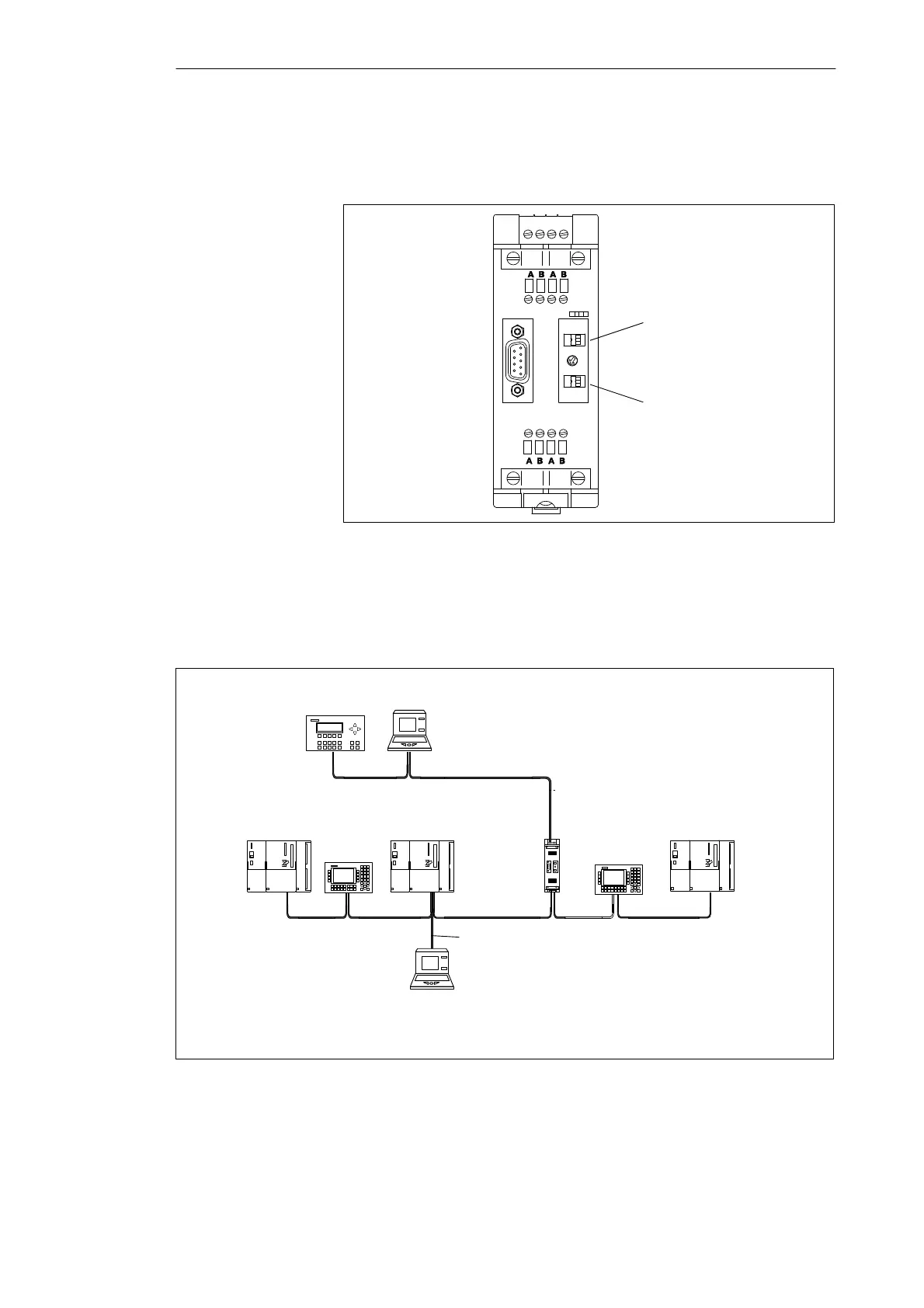
Figure 3-2 shows the switches on the RS 485 repeater for activating the
terminating resistor.
Terminating resistor
bus segment 1
Terminating resistor
bus segment 2
DC
24 V
L+ M PE M 5.2
SIEMENS
ON
ON
Figure 3-2 Terminating Resistor on the RS 485 Repeater
Figure 3-3 shows a possible MPI configuration in which the terminating
resistor must be activated.
RS 485
repeater
➀
Terminating resistor activated
S7-300
S7-300
C7
Connecting
cable
S7-300
OP 25
OP 25
PG
PG*
* Only connected during installation/maintenance via a tap line
À
À
À
À
Figure 3-3 Activating Terminating Resistors in an MPI Network
Terminating
Resistor on the RS
485 Repeater
Example of
Termination in an
MPI Network
Configuring an MPI Network