EasyManuals Logo

Siemens simatic c7-621 Hardware Installation Guide

Siemens simatic c7-621
138 pages
To Next Page IconTo Next Page
To Previous Page IconTo Previous Page
Page #87 background imageLoading...
Page #87 background image
7-5
C7-621 / C7-621 AS-i Control Systems
C79000-G7076-C621-01
7.1.1 Connecting Voltage and Current Sensors
The abbreviations in Figures 7-3 to 7-4 have the following meaning:
AIx-X: Measuring cable AIx-I or AIx-U
AIx-M: Measuring cable reference potential
M: Reference potential of the analog measuring circuit (functional
ground
)
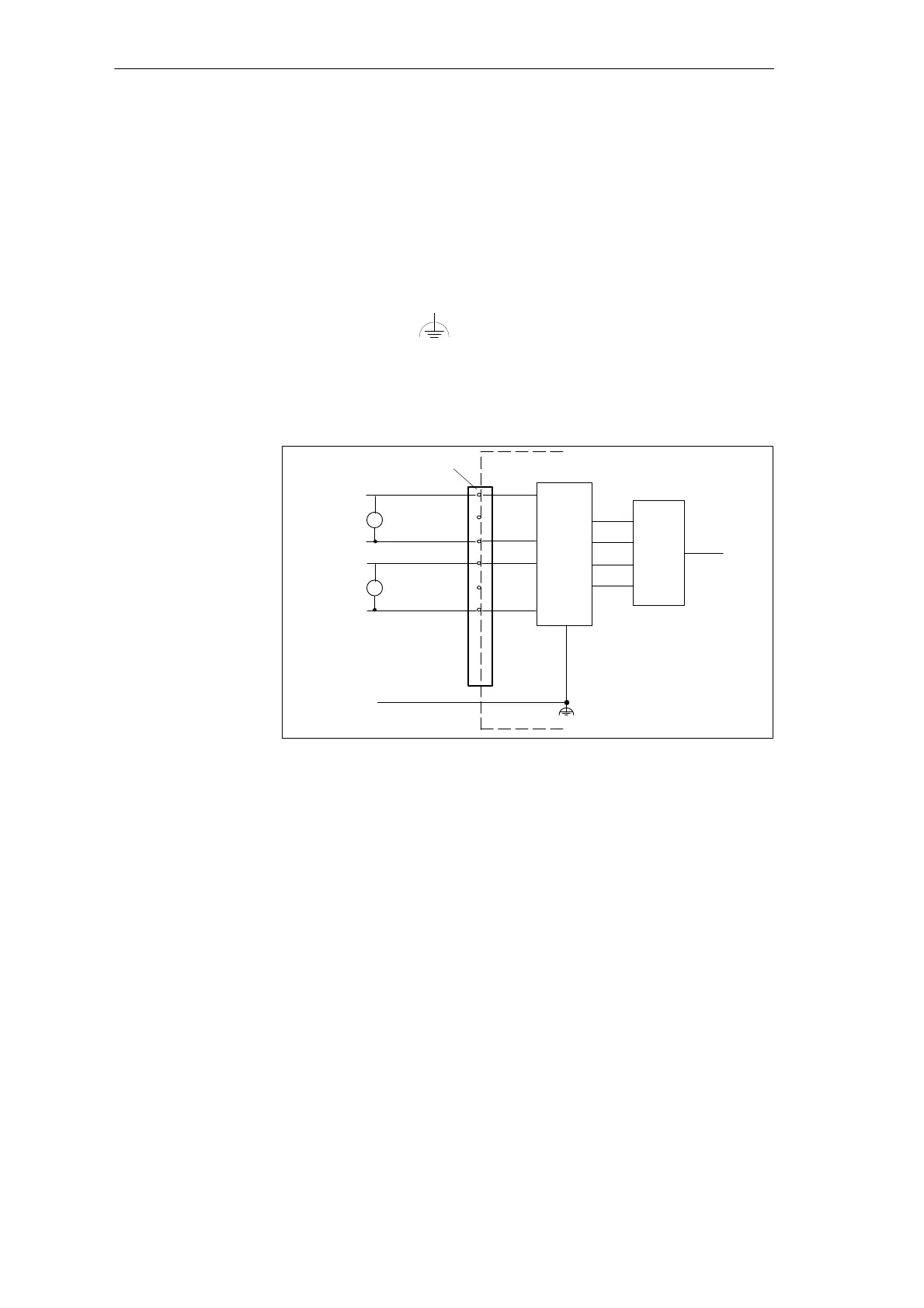
Figure 7-3 shows the connection of voltage sensors to a non-floating analog
input.
.
.
.
ADC
Logic
AI1-U
AI1-M
C7-CPU
+
-
U
AI2-U
AI2-M
U
+
-
Analog inputs
Functional ground
M
C7-621
Figure 7-3 Connecting Non-Isolated Sensors to a Non-Floating Analog Input
Abbreviations
Connecting
Voltage Sensors
C7-621 Analog I/Os

Table of Contents

Other manuals for Siemens simatic c7-621

Questions and Answers:

Question and Answer IconNeed help?

Do you have a question about the Siemens simatic c7-621 and is the answer not in the manual?

Siemens simatic c7-621 Specifications

General IconGeneral
BrandSiemens
Modelsimatic c7-621
CategoryControl Systems
LanguageEnglish

Related product manuals