3-13
C7-621 / C7-621 AS-i Control Systems
C79000-G7076-C621-01
3.5.1 PROFIBUS Bus Connector
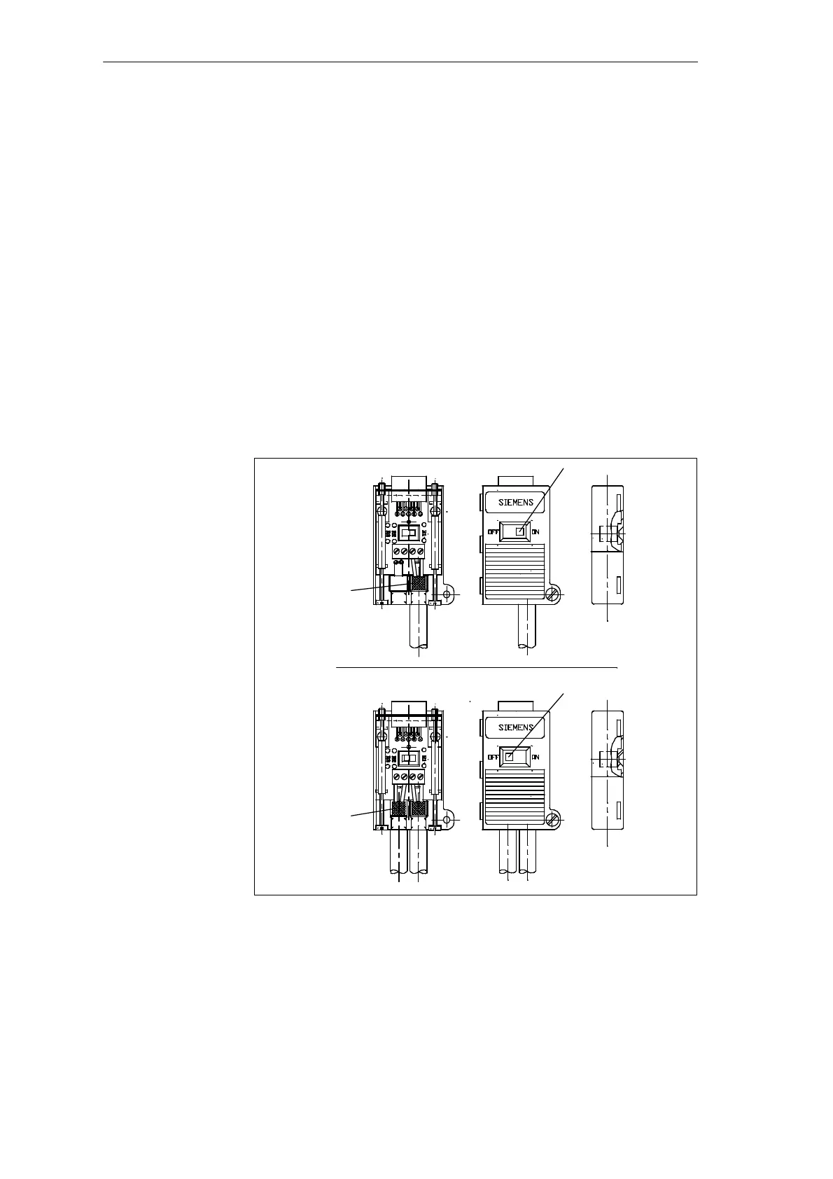
Figure 3-7 shows the PROFIBUS bus connector with order number
6GK1500-0EA00
Figure II:
Bus connector for the first and last node on the PROFIBUS network. The
cable can be connected either from the left or right.
① Switch setting for the first and last station on the PROFIBUS network:
“ON” (terminating resistor activated).
② The cable shield must lie on the bare metal.
Figure III:
① Terminator resistor deactivated.
② The cable shield must lie on bare metal.
①
②
②
①
II
III
Figure 3-7 Appearance of the PROFIBUS Bus Connector
Appearance
(6GK15000-0EA00.)
Configuring an MPI Network