2-7
C7-621 / C7-621 AS-i Control Systems
C79000-G7076-C621-01
2.4 Electrical Installation and Pinouts
To allow various components to be connected, the C7 is equipped with male
and female connectors.
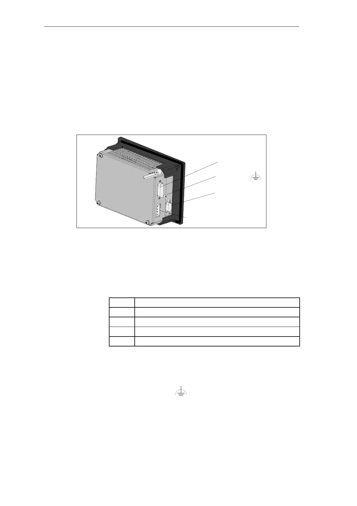
Figure 2-7 illustrates the connection of the C7 power supply for a C7-621.
The pinouts of the connectors are shown in the following tables.
Input 24 V DC
MPI
Functional
ground
P bus (IM 621)
Figure 2-7 Power Supply Connectors for the C7-621
The pinout of the input 24V DC (C7 power supply) and DI/DO power supply
is shown below. The C7 CPU, C7 OP and digital/analog sections (C7-621)
are supplied with power.
Table 2-1 Pinout
Pin
Function
L+ DC 24V
M (chassis M24V)
NC not connected
NC not connected
Connector for MPI-compliant components.
Connect functional ground
(see Figure 2-7) to the closest available
point of the closet chassis using a cable lug and a cable with a minimum
cross-sectional area of 4 mm
2
.
To connect an S7-300 expansion rack via an IM 621.
Overview
C7-621 and C7-621
AS-i
Input 24V DC
MPI
Functional Ground
P Bus (IM 621)
Installing and Preparing the C7