3-17
C7-621 / C7-621 AS-i Control Systems
C79000-G7076-C621-01
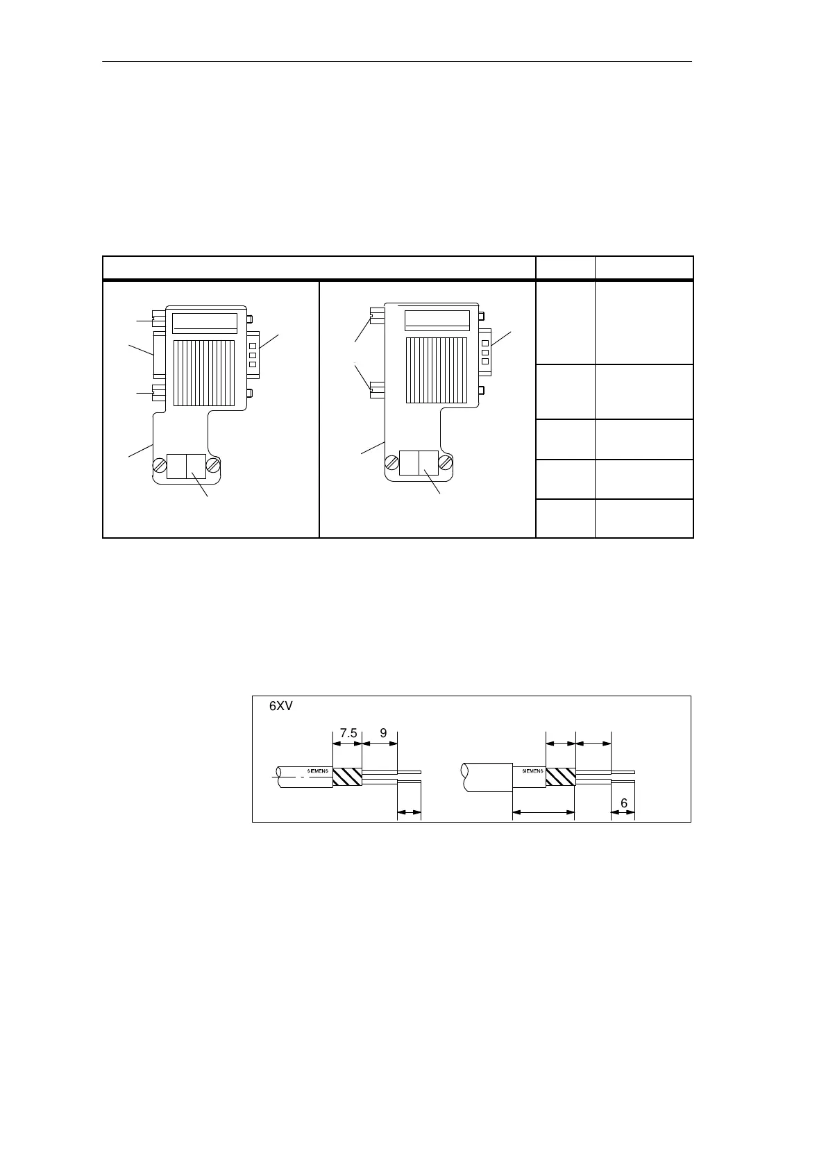
3.5.3 Bus Connector 6ES7 972-0B.10-0XA0
Table 3-6 shows the bus connector 6ES7 972-0B.10-0XA0
Table 3-6 Description and Functions of the Bus Connector 6ES7 972-0B.10-0XA0
Front View of the Bus Connector No. Function
With PG Interface
➀
➃
➄
Without PG Interface
➀
➄
➀
Connection to
the MPI,
PROFIBUS DP
interface (9-pin
sub D connector)
➄
➁
Connector for
the PROFIBUS
LAN cable
➂
Terminating
resistor
➂
➃
Interface for
PG/OP
➁
➄
Screws for fixing
to the node
To connect the bus connector 6ES7 972-0B.10-0XA0 to the PROFIBUS LAN
cable, follow the steps outlined below:
1. Cut the bus cable to the required length
2. Strip the insulation from the bus cable as shown in Figure 3-12.
7.5 9
6
7.5 9
6
6XV1 830–0AH10/-3BH10 6XV1 830–3AH10
16
Figure 3-12 Preparing the LAN Cable for Connecting the Bus Connector
6ES7 972-0B.10-0XA0
3. Open the housing of the bus connector by undoing the screws in the
housing.
4. Remove the cover.
Appearance
Preparing the
PROFIBUS LAN
Cable for the Bus
Connector
Configuring an MPI Network