3-16
C7-621 / C7-621 AS-i Control Systems
C79000-G7076-C621-01
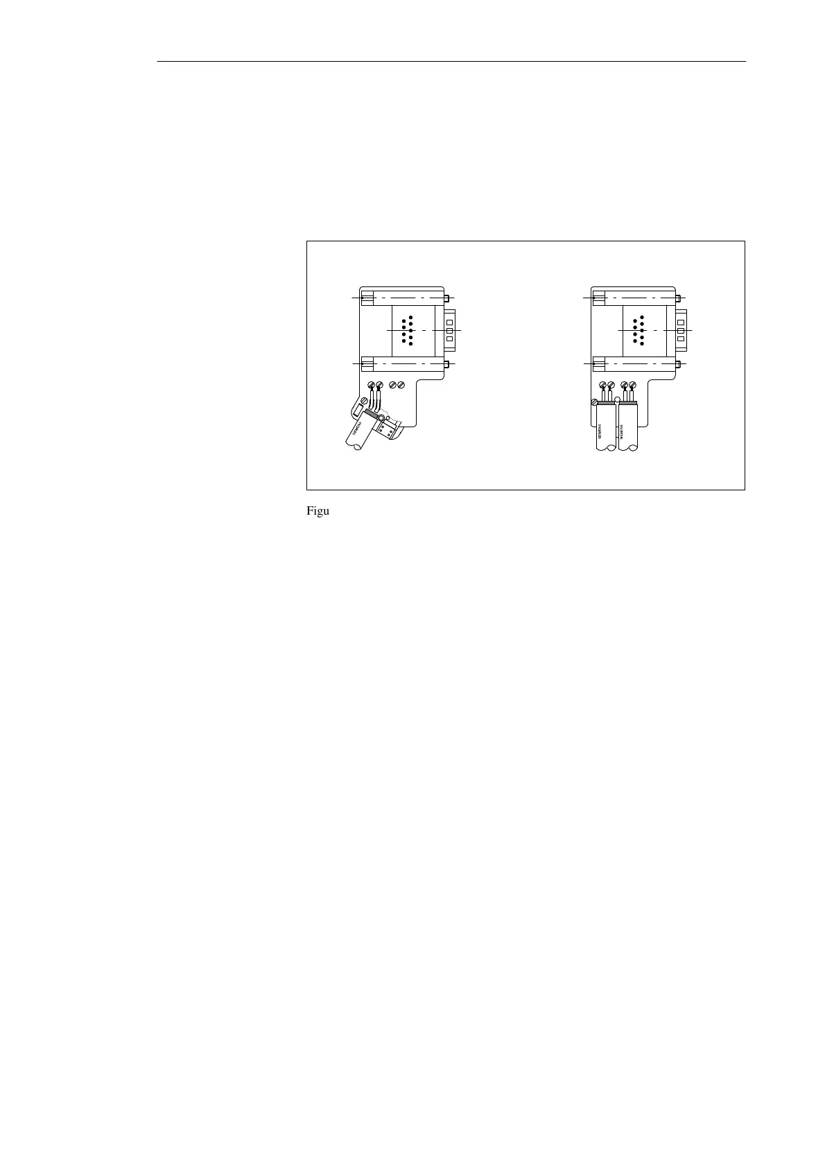
5. Fit the green and red wires into the screw terminal as shown in Figure
3-11.
Make sure that you always insert the same colored wire into the same
terminal on all connectors (for example the green wire into terminal A
and the red wire into terminal B, or vice-versa).
Bus cable connector for the first
and last stations on the bus
1
Bus cable connection for all
other stations on the bus
1 The bus cable can be connected either to the right or left!
A B A B A B A B
Figure 3-11 Fitting the Bus Connector (6ES7 972-0B.20 ...) to the LAN Cable
6. Screw down the hinged clamp again.
Make sure that the bare cable shield makes contact under the shield
clamp.
7. Secure the green and red wires in the screw terminal.
8. Close the cover of the bus connector.
9. Tighten the cover screw.
Configuring an MPI Network