3-18
C7-621 / C7-621 AS-i Control Systems
C79000-G7076-C621-01
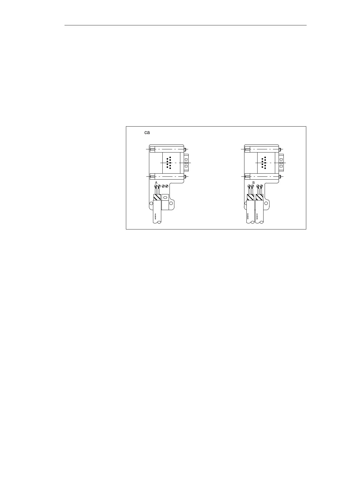
5. Fit the green and red wires into the screw terminal block as shown in
Figure 3-13.
Make sure that you always fit the same wires to the same terminal A or B
(for example always connect the green wire to terminal A and the red
wire to terminal B or vice-versa).
6. Press the cable sheath between the two clips. This fixes the cable in
position.
7. Tighten the screw terminals for the green and red wires.
A B A B
A B A B
Bus cable connection for first and
last node on the network.
LAN cable connection for all
other nodes in the network.
The LAN cable can be
connected either to the
right or left
Figure 3-13 Connecting the LAN Cable to the Bus Connector
6ES7 972-0B.10-0XA0
8. Close the housing again using the screws.
Make sure that the cable shield makes contact below the shield clamp.
Configuring an MPI Network

 Loading...


