2-8
C7-621 / C7-621 AS-i Control Systems
C79000-G7076-C621-01
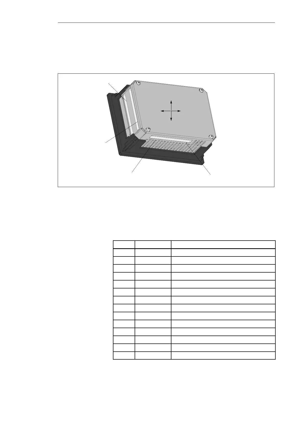
Figure 2-8 illustrates the C7-621 with digital and analog connectors. These
connectors only exist on the C7-621. The pinouts of the connectors are
shown in the following tables.
Analog input
Analog output
Digital output (bottom)
Digital input (top)
top
bottom
left right
Figure 2-8 View of a C7-621 with External I/O Ports
Table 2-2 Pinout of the Digital Inputs
Pin
Signal Function
0.0 I124.0 Digital input 0
0.1 I124.1 Digital input 1
0.2 I124.2 Digital input 2
0.3 I124.3 Digital input 3
0.4 I124.4 Digital input 4
0.5 I124.5 Digital input 5
0.6 I124.6 Digital input 6
0.7 I124.7 Digital input 7
1.0 I125.0 Digital input 8
1.1 I125.1 Digital input 9
1.2 I125.2 Digital input 10
1.3 I125.3 Digital input 11
1.4 I125.4 Digital input 12
1.5 I125.5 Digital input 13
C7-621
Digital Input
Installing and Preparing the C7