7-3
C7-621 / C7-621 AS-i Control Systems
C79000-G7076-C621-01
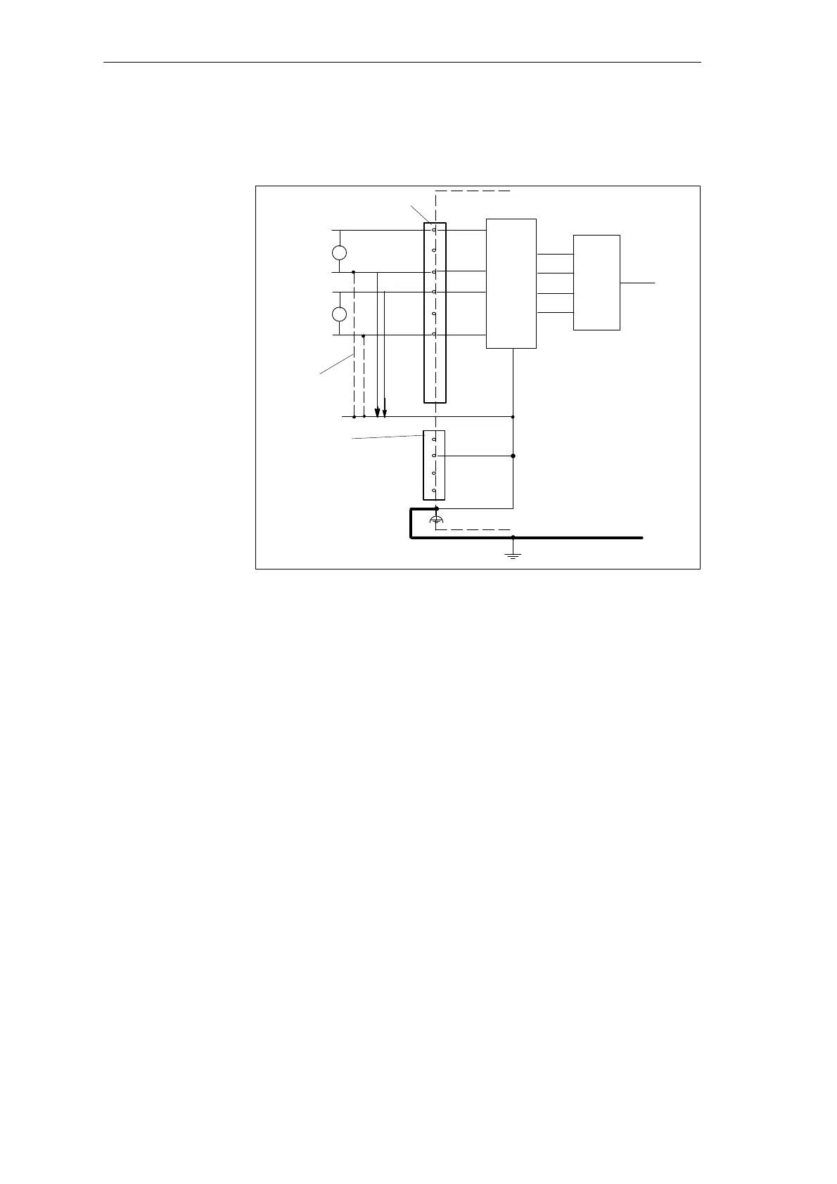
Figure 7-1 shows the connection of isolated sensors to a non-floating analog
input.
.
.
.
Isolated
sensors
Input 24V DC
Grounding bar
ADC
Logic
AI1-U
AI1-M
C7-CPU
+
-
U
Recommended
connection
U
CM
AI2-U
AI2-M
U
+
-
L+
M
NC
NC
Analog inputs
Functional ground
M
C7-621
Figure 7-1 Connection of Isolated Sensors to a Non-Floating Analog Input
Non-isolated sensors are connected to ground locally. Due to local conditions
or noise, potential differences (static or dynamic) can occur between the
locally distributed measuring points. To avoid these potential differences, you
should install equipotential bonding cables between the measuring points.
Potential differences U
CM
(static or dynamic) can also occur between the
measuring cables AIx-M of the input channels and the reference point of the
measuring circuit M. This potential difference must not exceed the maximum
permitted value. If it is possible that this will exceed the maximum permitted
value for U
CM
or if you cannot measure the potential difference exactly,
AIx-M must be connected to M.
Non-Isolated
Sensors
C7-621 Analog I/Os