EasyManuals Logo

Siemens simatic c7-621 Hardware Installation Guide

Siemens simatic c7-621
138 pages
To Next Page IconTo Next Page
To Previous Page IconTo Previous Page
Page #94 background imageLoading...
Page #94 background image
7-12
C7-621 / C7-621 AS-i Control Systems
C79000-G7076-C621-01
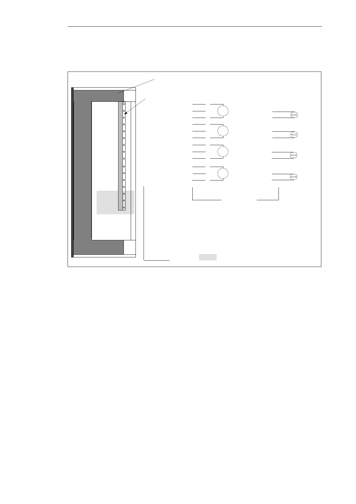
Figure 7-7 shows the terminal diagram of the analog inputs
Connection
Voltage measurement
Analog inputs
Pin name
AI1-U
AI1-I
AI1-M
AI2-U
AI2-I
AI2-M
AI3-U
AI3-I
AI3-M
AI4-U
AI4-I
2
1
3
V
5
4
6
V
8
7
9
V
11
10
12
V
Current measurement
2
1
3
5
4
6
8
7
9
11
10
12
AI4-M
View from the right of the C7-621
These shaded sections are irrelevant
for this example.
Figure 7-7 Terminal Diagram of the Analog Inputs
For more information about analog addresses, refer to Volume 2, Chapter 4.
Terminal Diagram
Analog Addresses
C7-621 Analog I/Os

Table of Contents

Other manuals for Siemens simatic c7-621

Questions and Answers:

Question and Answer IconNeed help?

Do you have a question about the Siemens simatic c7-621 and is the answer not in the manual?

Siemens simatic c7-621 Specifications

General IconGeneral
BrandSiemens
Modelsimatic c7-621
CategoryControl Systems
LanguageEnglish

Related product manuals