Installing and Wiring the C7-635
3-17
C7-635 Control System
A5E00155581-04
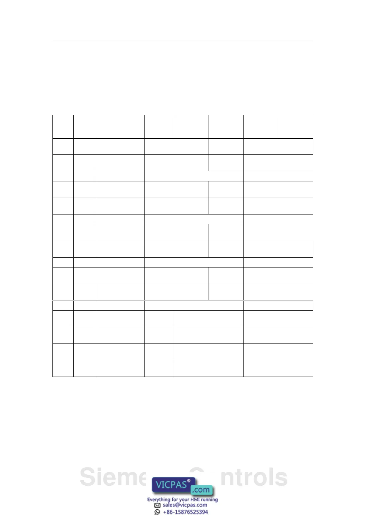
I/O Connector X 11
For the technological functions, the meaning of the inputs is described in the
columns “Counting”, “Frequency Measuring”, “Pulse Width Modulation”, “Analog
Positioning”, and “Digital Positioning”.
Table 3-7 Connector Pin Assignments I/O Connector X11
Pin
Name
Signal Description Counting Frequency
Measuring
Pulse
Width
Modulation
Analog
Positioning
Digital
Positioning
1 DI+0.0 Digital input 0 Channel 0: Trace
A/Pulse
– Sensor Signal A
2 DI+0.1 Digital input 1 Channel 0: Trace
B/Direction
– Sensor Signal B
3 DI+0.2 Digital input 2 Channel 0: Hardware Gate Sensor Signal N
4 DI+0.3 Digital input 3 Channel 1: Trace
A/Pulse
Length Measurement
5 DI+0.4 Digital input 4 Channel 1: Trace
B/Direction
– Home position switch
6 DI+0.5 Digital input 5 Channel 1: Hardware Gate –
7 DI+0.6 Digital input 6 Channel 2: Trace
A/Pulse
– –
8 DI+0.7 Digital input 7 Channel 2: Trace
B/Direction
– –
9 DI+1.0 Digital input 8 Channel 2: Hardware Gate –
10 DI+1.1 Digital input 9 Channel 3: Trace
A/Pulse
– –
11 DI+1.2 Digital input 10 Channel 3: Trace
B/Direction
– –
12 DI+1.3 Digital input 11 Channel 3: Hardware Gate –
13 DI+1.4 Digital input 12 Channel
0: Latch
– –
14 DI+1.5 Digital input 13 Channel
1: Latch
– –
15 DI+1.6 Digital input 14 Channel
2: Latch
– –
16 DI+1.7 Digital input 15 Channel
3: Latch
–
Siemens Controls