Product overview
2.2 Operator controls and display elements
Communication module CM 8x IO-Link + DI 4x24VDC M12-L (6ES7148-6JG00-0BB0
Equipment Manual, 09/2020, A5E49284833-AA
13
2.2 Operator controls and display elements
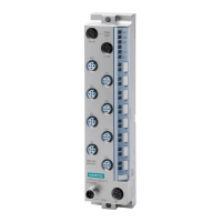
The following figure shows the operator controls and display elements of the CM 8xIO-Link +
DI 4x24VDC M12-L communication module.
PN/MF (LAN): Sockets for connecting PROFINET
RN/NS: RUN/network status LED
ER/MS: ERROR/module status LED
MT/IO: MAINT/IO status LED
PWR: LED display for load voltage 2L+
P1 LK: LINK port status LED
P2 LK: LINK port status LED
IO-L1 to IO-L8: LED indicators for channel status IO-Link
DI0 to DI3: LED indicators for channel status digital input
⑩
X10 to X13: Sockets for IO-Link port Class A and DI
X14 to X17: Sockets for IO-Link port Class B
X80: Connector for infeed of the supply voltages
X81: Socket for loop-through of the supply voltages
Figure 2-2 Operator controls and display elements

 Loading...


