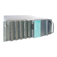
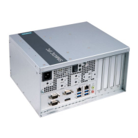
SIMATIC IPC847D
A5E38018732-AD, 09/2017
23
Interrupt assignment of the slot connectors on the bus board
Changes and supplements to section 8.5.2.3 of the operating instructions.
Note
All system resources (hardware addresses, memory allocation, interrupt assignment, DMA channels) are assigned
dynamically by the BIOS or the Windows operating system, depending on the hardware equipment, drivers
, installed
expansion cards and connected external devices.
Assignment is automatic and depends on the demanded resources of the connected devices and the inserted modules. Due
to this configuration dependency, clear statements can only be made by determin
ing them in relation to the system in the
final configuration. Resources may be viewed as follows under Windows:
Press the "Windows key" and "R" simultaneously.
The "Run" dialog box opens.
Enter "msinfo32" in the "Open" field.
3. Confirm your entry with "OK".
The following tables 1, 2 and 3 are examples of assignments if the system is operated in PIC mode (legacy mode).
The tables apply to the configuration with an expansion module which uses only one interrupt, e.g. PCI module which uses
the INTA# interrupt, connected to pin A6 of the PCI bus connector.
Bus board 7x PCI, 3x PCIe x4, 1x PCIe x16
Affected order numbers: 6AG4114-2xxx0-xxxx and 6AG4114-2xxx2-xxxx
Type PCIe
4x
PCH
1 lane*
PCIe
4x
PCH
1 lane*
PCIe
4x
PCH
1 lane*
PCI
PCI
PCI
PCIe
x16
CPU
16
PCI
behind
bridge
PCI
behind
bridge
PCI
behind
bridge
PCI
behind
bridge
* Number of active PCIe lanes in the direct connector of the slot
Bus board 3x PCI, 3x PCIe x4, 5x PCIe x16
Affected order numbers: 6AG4114-2xxx1-xxxx and 6AG4114-2xxx3-xxxx
Type PCIe
4x
PCH
4 lanes*
PCIe
4x
PCH
4 lanes*
PCIe
4x
PCH
4 lanes*
PCIe
x16
PCH
switched
PCIe
x16
PCH
4 lanes*
switched
PCIe
x16
CPU
4 lanes*
PCIe
x16
CPU
4 lanes*
PCIe
x16
CPU
8 lanes*
PCI
PCI
PCI
* Number of active PCIe lanes in the direct connec
tor of the slot
** For details, see Table 3