Supplementary information
18.13 Link-up and update sequence
CPU 410 Process Automation/CPU 410 SMART
344 System Manual, 05/2017, A5E31622160-AC
Flow chart of the link-up and update operation
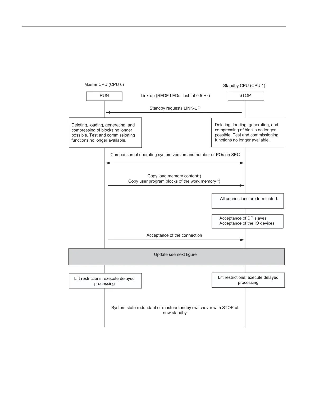
The figure below outlines the general sequence of the link-up and update. In the initial
situation, the master is in solo operation. In the figure, CPU 0 is assumed to be the master
CPU.
Figure 18-22 Sequence of link-up and update
*) If the "Switchover to CPU with modified configuration" option is set, the content of the load
memory is not copied; what is copied from the user program blocks of the work memory
(OBs, FCs, FBs, DBs, SDBs) of the master CPU is listed in Chapter Switch to CPU with
modified configuration (Page 351)
 Loading...


