Connection examples for redundant I/Os
C.17 SM 421; DI 32 x DC 24 V, 6ES7 421–1BL01–0AB0
CPU 410 Process Automation/CPU 410 SMART
System Manual, 05/2017, A5E31622160-AC
407
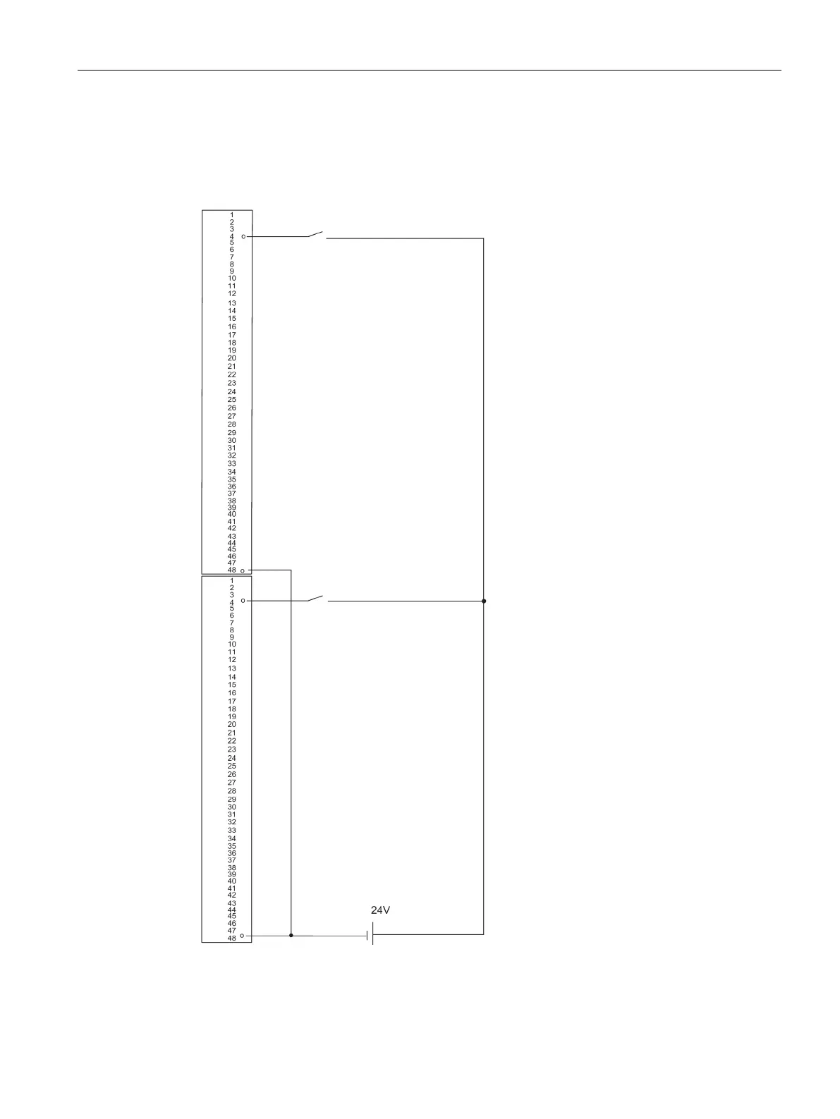
SM 421; DI 32 x DC 24 V, 6ES7 421–1BL01–0AB0
The diagram below shows the connection of two redundant encoders to two
SM 421; D1 32 x 24 V. The encoders are connected to channel 0.
Figure C-15 Example of an interconnection with SM 421; DI 32 x 24 V
 Loading...


