I/O configuration variants
6.7 Connection of two-channel I/O to the PROFIBUS DP interface
CPU 410 Process Automation/CPU 410 SMART
94 System Manual, 05/2017, A5E31622160-AC
Redundant analog input modules for direct current measurement
The following applies for wiring analog input modules:
● Suitable encoder types: active 4-wire and passive 2-wire transmitters with output ranges
+/-20 mA, 0 to 20 mA, and 4 to 20 mA. 2-wire transmitters are powered by an external
auxiliary voltage.
● The "wire break" diagnostics function supports only the 4...20 mA input range. All other
unipolar or bipolar ranges are excluded in this case.
● Suitable diodes include the types of the BZX85 or 1N47..A series (1.3 W Zener diodes)
with the voltages specified for the modules. When selecting other elements, make sure
that the reverse current is as low as possible.
● A fundamental measuring error of max. 1 µA results from this type of circuit and the
specified diodes due to the reverse current. In the 20 mA range and at a resolution of
16 bits, this value leads to an error of < 2 bits. Individual analog inputs in the circuit above
lead to an additional error, which may be listed in the constraints. The errors specified in
the manual must be added to these errors for all modules.
● The 4-wire transmitters used must be capable of driving the load resulting from the circuit
above. You will find details in the technical specifications of the individual modules.
● When connecting 2-wire transmitters, please note that the Zener diode circuit weighs
heavily in the power budget of the transmitter. The required input voltages are therefore
included in the technical specifications of the individual modules. Together with the
inherent supply specified on the transmitter data sheet, the minimum supply voltage is
calculated to L+ > U
e-2w
+ U
IS-TR
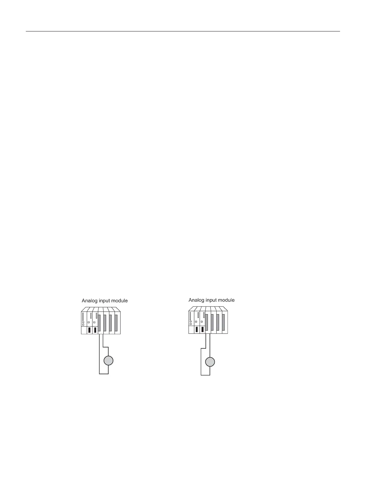
Redundant analog input modules with redundant encoders
With double-redundant encoders, it is better to use fail-safe analog input modules in a 1-out-
of-2 configuration:
Figure 6-18 Fault-tolerant analog input modules in 1-out-of-2 configuration with two encoders
The use of redundant encoders also increases their availability.
A discrepancy analysis also detects external errors, except for the failure of a non-redundant
load voltage supply.
You will find interconnection examples in Appendix Connection examples for redundant I/Os
(Page 391).
The general comments made at the beginning of this documentation apply.
 Loading...


